
Alternating current-direct current micro-grid system on basis of electricity energy collector

A microgrid, AC and DC technology, applied to a single AC network with different frequencies, electrical components, circuit devices, etc., can solve problems such as unfavorable coordination and optimization of energy management, difficulty in centralized management, and unfavorable microgrid construction, etc. The effect of unified and coordinated management, simplified structure and control process, and improved power quality

Inactive Publication Date: 2015-04-29
STATE GRID CORP OF CHINA +1
View PDF6 Cites 13 Cited by
  • Summary
  • Abstract
  • Description
  • Claims
  • Application Information

AI Technical Summary

Problems solved by technology

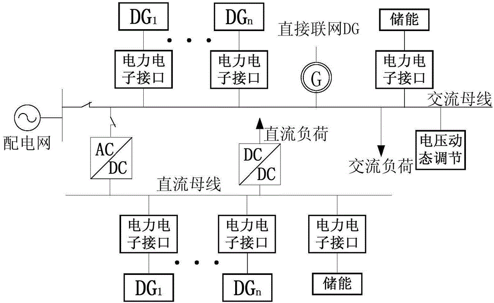
figure 1 It is a structural diagram of a traditional AC microgrid; although this method solves the access of distributed power sources within a certain range, due to the various grid-connected converters, it is necessary to solve the problems of distributed power machine-side control and energy transfer and also take into account the power grid Tracking and grid-connection problems make centralized management difficult, which is not conducive to the coordination and optimization of energy management, and the efficiency is low, and other power quality control equipment is required. This method is not conducive to the construction of micro-grids, and it is even more difficult to realize the plug-and-play function

Method used


Image

  • Alternating current-direct current micro-grid system on basis of electricity energy collector
  • Alternating current-direct current micro-grid system on basis of electricity energy collector
  • Alternating current-direct current micro-grid system on basis of electricity energy collector

Examples


Embodiment Construction

[0021] The specific implementation manners of the present invention will be further described in detail below in conjunction with the accompanying drawings.

[0022] In order to thoroughly understand the embodiments of the present invention, the detailed structure will be set forth in the following description. Obviously, the practice of the embodiments of the invention is not limited to specific details familiar to those skilled in the art. Preferred embodiments of the present invention are described in detail below, however, the present invention may have other embodiments besides these detailed descriptions.

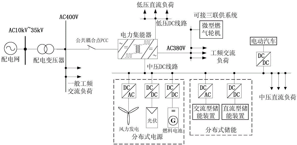
[0023] Such as figure 2 as shown, figure 2 It is an architecture diagram of the AC / DC microgrid system based on the electric energy collector of the present invention. The AC / DC microgrid system described in the figure is sequentially connected by a distribution network, a distribution transformer, and a load. A power energy collector is arranged between the load...


PUM


Abstract

The invention discloses an alternating current-direct current micro-grid system on the basis of an electricity energy collector. The alternating current-direct current micro-grid system comprises a power distribution network, a power distribution transformer, a distributed power source, distributed energy storage and loads which are sequentially connected with one another. The electricity energy collector is arranged among the loads, the distributed power source, the distributed energy storage and the transformer and is connected with an alternating-current 400V bus on a low-voltage side of the power distribution transformer by a point of common coupling (PCC) of a micro-grid. The alternating current-direct current micro-grid system has the advantages that the flexible all-controllable electricity energy collector is based on power electronic technologies, the micro-grid system on the basis of the power energy collector has electricity energy collector unified management and grid connection functions, direct-current and alternating-current circuits can be constructed in a unified manner, the quality of electric energy can be controlled in a unified manner, plug-and-play access of the distributed power source can be facilitated, and the alternating current-direct current micro-grid system brings convenience for unified coordination management and efficiency improvement.

Description

technical field [0001] The invention relates to flexible AC power transmission and distribution technology, in particular to an AC-DC microgrid system based on a power collector. Background technique [0002] Due to the intermittent and random characteristics of wind power, solar power and other green renewable energy power generation, traditional power equipment, grid structure and operation technology are increasingly unable to accommodate more and more distributed renewable power sources. Access to the distribution network is an effective method to solve the high penetration rate of distributed power generation access to the distribution network. However, the current way of constructing a microgrid basically adopts the method that each distributed power source uses its own power electronic grid-connected inverter to connect to the AC line on the low-voltage side of the distribution transformer or uses a power electronic rectifier to increase the DC line. The power supply...

Claims


Application Information

Patent Timeline
IPC IPC(8): H02J3/38H02J3/02
CPCH02J3/381H02J3/02
Inventor 段青盛万兴梁英史常凯孟晓丽吕志鹏马春艳李玉凌
Owner STATE GRID CORP OF CHINA
Learn More