
Magnetic coupling resonance wireless power transmission device achieving self-optimization of frequency and dynamic tuning

A technology of magnetic coupling resonance and wireless power transmission, applied in circuit devices, electrical components, electromagnetic wave systems, etc., can solve problems such as adverse effects of system tuning, difficult to solve detuning, easy detuning of the receiving system, etc., and achieve the goal of improving power output performance Effect

Inactive Publication Date: 2015-04-29
SOUTH CHINA UNIV OF TECH +1
View PDF5 Cites 31 Cited by
  • Summary
  • Abstract
  • Description
  • Claims
  • Application Information

AI Technical Summary

Problems solved by technology

The optimization of the magnetic resonance coupling wireless power transmission device urgently needs to solve the following problems: when the load changes and the position of the transmitting coil and the receiving coil changes, the transmission power and efficiency can meet the requirements and the influence on the efficiency of the high-frequency power supply; when the high-frequency power supply When the frequency changes, the inductance, capacitance and parasitic parameter values ​​in the transmitting module and receiving module will change, which will have an adverse effect on system tuning; in theoretical analysis, the load of the receiving system is often regarded as a pure resistive load, while the actual load is often It is a resistive-inductive or resistive-capacitive load. Changes in load characteristics often make the receiving system more prone to detuning, and the detuning problem is often more difficult to solve

Method used

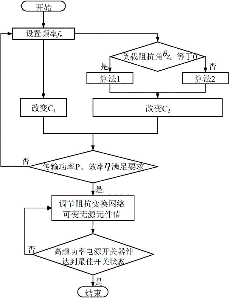
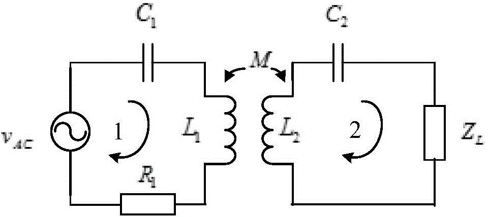

Image

  • Magnetic coupling resonance wireless power transmission device achieving self-optimization of frequency and dynamic tuning
  • Magnetic coupling resonance wireless power transmission device achieving self-optimization of frequency and dynamic tuning
  • Magnetic coupling resonance wireless power transmission device achieving self-optimization of frequency and dynamic tuning

Examples


Embodiment Construction

[0028] specific implementation plan

[0029] The specific implementation in the embodiments of the present invention will be described in detail below in conjunction with the drawings in the embodiments of the present invention, but the described embodiments are only some of the embodiments of the present invention, not all of them. It should be pointed out that, if there are any processes or symbols that are not specifically described in detail below, those skilled in the art can refer to the prior art to realize or understand according to the usual expressions.

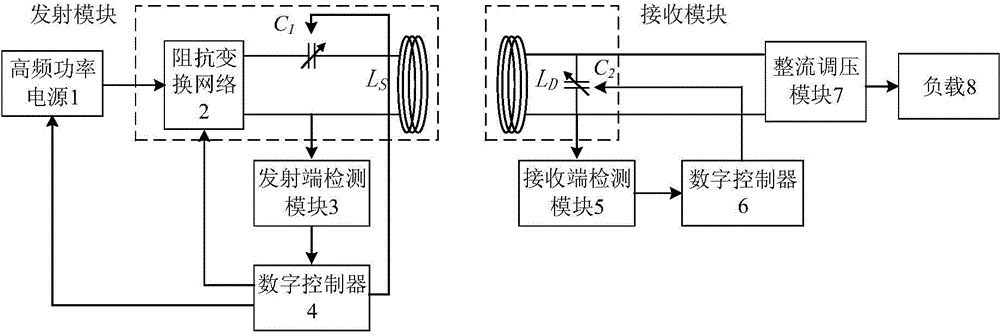
[0030] like figure 1 As shown, it is a structural schematic diagram of the frequency self-optimizing dynamic tuning magnetic coupling resonant wireless power transmission device of the present invention, and the working principle of the present invention will be described below in conjunction with this figure.

[0031] figure 1 Among them, the first digital controller 4 obtains the optimal frequency according to t...


PUM


Abstract

The invention provides a magnetic coupling resonance wireless power transmission device achieving self-optimization of frequency and dynamic tuning. The device comprises a high-frequency power power source, a transmitting module, a receiving module, a transmitting end detecting module, a receiving end detecting module, a digital controller, a rectification and voltage regulation module and a load. The magnetic coupling resonance wireless power transmission device is characterized in that the optimized frequency can be followed in real time according to the change of a coupling magnetic field of a transmitting coil and a receiving coil, the change of main circuit parameters and the change of the load, so that the power and efficiency of the whole system (from the power source to the load) are improved, the magnetic coupling resonance wireless power transmission device achieving self-optimization of frequency and dynamic tuning can be applied to the solution for the detuning problem under the fixed frequency condition and can also be applied to the occasions with variable frequency and stable power and efficiency, and the wide application prospect is achieved.

Description

technical field [0001] The invention relates to the technical field of magnetic resonance coupling wireless power transmission devices, in particular to a wireless power transmission device that can self-adjust frequency and dynamically tune according to power and efficiency requirements. Background technique [0002] In 2006, researchers at the Massachusetts Institute of Technology (MIT) successfully lit a 60W light bulb at a distance of about 2m with a 40% efficiency using a magnetic resonance coupling wireless power transmission device. The dilemma faced by wireless power transmission has triggered an upsurge in research and optimization of magnetic resonance coupled wireless power transmission devices. [0003] The magnetic resonance coupling wireless power transmission device is a device that uses magnetic resonance coupling technology to realize wireless transmission of electric energy from the power source to the load. The magnetic resonance coupling wireless power t...

Claims


Application Information

Patent Timeline
IPC IPC(8): H02J17/00H02J50/12
Inventor 肖文勋周佳丽张波郭上华刘红伟
Owner SOUTH CHINA UNIV OF TECH
Learn More