
Pressure sensor and tubing kit for monitoring blood pressure during medical contrast agent injection procedure

A pressure sensor and pressure technology, applied in the field of medical injection systems, can solve problems such as blood pressure monitoring distortion, air embolism, and reducing the natural frequency response of pressure sensors

Inactive Publication Date: 2015-04-29
ACIST MEDICAL SYST
View PDF5 Cites 10 Cited by
  • Summary
  • Abstract
  • Description
  • Claims
  • Application Information

AI Technical Summary

Problems solved by technology

Those skilled in the art will appreciate that the presence of significant volumes of air in the fluid circuit not only poses a risk of air embolism in the patient's vasculature during injection of contrast media, but may also contribute to the fluid circuit by increasing its compliance. (It can effectively reduce the natural frequency response of the pressure sensor) so that the aforementioned blood pressure monitoring is distorted

Method used


Image

  • Pressure sensor and tubing kit for monitoring blood pressure during medical contrast agent injection procedure
  • Pressure sensor and tubing kit for monitoring blood pressure during medical contrast agent injection procedure
  • Pressure sensor and tubing kit for monitoring blood pressure during medical contrast agent injection procedure

Examples


Embodiment Construction

[0021] The following detailed description is exemplary in nature and is not intended to limit the scope, applicability, or configuration of the invention in any way. Rather, the following description provides practical explanations for implementing the exemplary methods and embodiments. Examples of constructions, materials and dimensions are provided for selected elements and for all other elements are those known to those skilled in the art of the invention. Those skilled in the art will recognize that many of the examples provided have suitable alternatives that can be used.

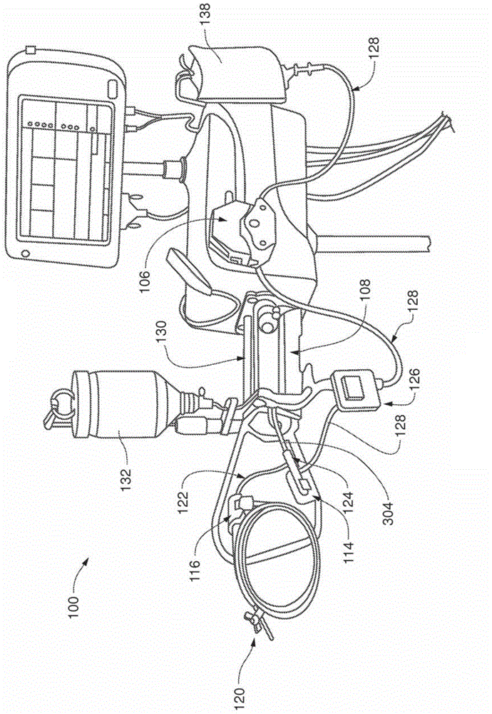
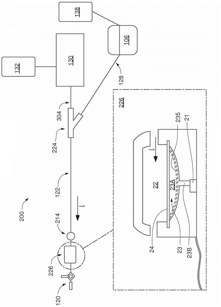
[0022] figure 2 is a block diagram of an injection system fluid circuit 200, along with an enlarged schematic cross-sectional view of a pressure transducer assembly 226 included therein and configured according to some embodiments and methods. Fluid circuit 200 is similar to figure 1 As shown in system 100 in FIG. 2 , however, instead of being integrated in fluid circuit line 228 like pressure tran...


PUM

PropertyMeasurementUnit
Diameteraaaaaaaaaa

Abstract

A pressure sensor, for example, employed by a medical injection system for monitoring blood pressure, is isolated from relatively high pressures by a volume of a compressible medium, preferably air, or other suitable gas. The volume fills an entirety of a cavity of a pressure transducer assembly, and is enclosed between a pressure transmission interface of the assembly and the pressure sensor. The pressure transducer assembly is integrated into a fluid circuit such that the pressure transmission interface is exposed to flow through the fluid circuit. The cavity of the assembly has a configuration that allows transmission of a patient's blood pressure from the fluid circuit, via the interface and gas volume, to the pressure sensor, yet prevents transmission of the relatively high pressures, for example, injection pressures. The pressure transducer assembly may be part of a disposable fluid circuit subassembly, for example, packaged as a kit.

Description

technical field [0001] The present disclosure relates to medical injection systems and more particularly to devices and methods for isolating blood pressure monitoring sensors thereof. Background technique [0002] Medical injection systems, such as those used to deliver contrast media into a patient's vasculature for medical imaging, typically include pressure sensors integrated into the system's fluid circuit for the purpose of monitoring the patient's blood pressure during the imaging procedure. However, the pressure at which the contrast agent is injected is significantly higher (i.e., up to 1200 psi) than the monitored blood pressure (i.e., between 0 and 5 psi) By isolating the portion through which a typical blood pressure monitoring pressure sensor is protected from exposure to this high injection pressure. An example of such a medical injection system, ACIST CV i TM system, shown in figure 1 middle. [0003] figure 1 is a perspective view of an exemplary medica...

Claims


Application Information

Patent Timeline
IPC IPC(8): A61M5/00A61B5/021A61B5/0215G01L7/08G01L9/00G01L19/00G01L19/06
CPCA61M5/007A61M2205/3344A61M2205/3362A61M2230/30A61B5/02141A61B5/0215A61B5/4839A61B5/7217A61M5/16854
Inventor S·D·尼斯特罗姆D·D·斯科特
Owner ACIST MEDICAL SYST
Learn More