Disc brake pad mounting and retention system and method

A technology of disc brakes and brake pads, which is applied in the direction of brake types, brake components, axial brakes, etc., to achieve the effect of increasing strength and increasing the service life of calipers

Active Publication Date: 2015-04-29
BENDIKS SPAJSER FAUNDEJSHN BREJK LLK
View PDF6 Cites 7 Cited by
  • Summary
  • Abstract
  • Description
  • Claims
  • Application Information

AI Technical Summary

Problems solved by technology

[0007] The present invention solves these and other problems by providing a brake pad mount and retainer and method of installation and removal that makes it easier to install and remove brake pads in situ without the need for brake calipers Removal or other significant brake disassembly work

Method used


Image

  • Disc brake pad mounting and retention system and method
  • Disc brake pad mounting and retention system and method
  • Disc brake pad mounting and retention system and method

Examples


Embodiment Construction

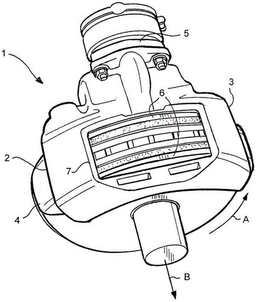
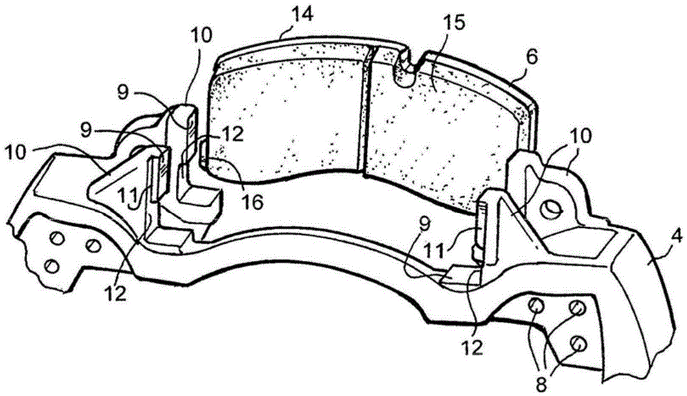
[0021] exist figure 1 In the illustrated embodiment, a disc brake 1 for a commercial vehicle comprises a brake disc 2 and a brake caliper 3 straddling the brake disc 2 . The caliper 3 is usually attached via a torque plate or brake mount (not shown) to a caliper base bracket 4 which in turn is secured to the vehicle wheel axle. The caliper 3 is actuated by an actuator 5, in this embodiment a spring brake actuator, controlled by the vehicle's pneumatic pressure. The actuator 5 acts on a brake pad application mechanism contained within the caliper 3 to press the brake pad 6 against the brake disc 2 to decelerate the vehicle. The invention is not limited to pneumatic actuators (e.g. electrically driven actuators could be used) or to particular types of brake caliper / mount arrangements (e.g. fixed bracket and sliding caliper with single sided brake pad application mechanism, or with fixing brackets and fixing calipers for the brake pad application mechanism on both sides). In t...


PUM


Abstract

A brake pad for a disk brake comprising a brake pad backing plate(14), a brake pad lining material affixed to a brake diskside of the brake pad backing plate, wherein the brake pad backing plate includes a brake pad retaining feature (16, 16a) on at least two lateral sides configured to permit brake pad insertion through an installed brake caliper in a radially-inward direction and translation of the brake pad toward a brake disk of the disk brake while engaging at least one lateral brake pad receiving feature, and each brake pad retaining feature (16, 16a) on each of the at least two lateral sides is asymmetric to at least one other brake pad retaining feature on at least one of the at least two lateral sides.

Description

technical field [0001] The present invention relates to a disc brake for a vehicle, and in particular to a system and method for installing, removing and retaining brake pads in a disc brake, such as a pneumatic disc for commercial vehicles type brake. Background technique [0002] Pneumatic disc brakes have undergone development and application on commercial vehicles since at least the 1970s and have begun to replace drum brakes due to advantages in areas such as cooling, fade resistance, and reliability in use. German patent application DE 40 32 886 A1, and in particular the document's figure 1 , discloses an example of such an air disc brake. In this design, a pneumatic diaphragm chamber (pneumatic actuator) is attached to the rear surface of the disc brake caliper housing, and the brake actuation force is applied to the brake actuator rod inside the caliper through a linear actuator rod. The brake's actuator rod in turn transmits and multiplies the force exerted by th...

Claims


Application Information

Patent Timeline
Patent Type & Authority Applications(China)
IPC IPC(8): F16D65/092
CPCF16D65/092F16D2065/026F16D65/095F16D2055/0008
Inventor 罗纳尔多·S·普兰坦哈里什·拉达克里希南丹尼斯·A·沃尔夫理查德·L·兰兹威尔·E·罗伯茨史蒂芬·C·贝尔
Owner BENDIKS SPAJSER FAUNDEJSHN BREJK LLK
Why Eureka
Try Eureka