
Diaphragm coating machine

A coating machine and diaphragm technology, which is applied to devices for coating liquid on surfaces, coatings, pretreatment surfaces, etc., can solve the problems of high diaphragm, poor heat resistance and mechanical strength, and poor mechanical strength of diaphragm coils. , to achieve the effect of highlighting social benefits and saving investment

Inactive Publication Date: 2015-05-06
TIANJIN LIHAO TECH DEV
View PDF0 Cites 8 Cited by
  • Summary
  • Abstract
  • Description
  • Claims
  • Application Information

AI Technical Summary

Problems solved by technology

[0002] The coating modification of lithium-ion battery diaphragm is a hot spot and a difficult point in the lithium battery industry at present. The hot point is that the heat resistance and mechanical strength of the lithium battery diaphragm itself are poor, which can no longer meet the needs of high specific energy density and large capacity battery systems. Therefore, improving its thermal and mechanical properties by coating modification has become an important direction for the development of diaphragm materials at home and abroad.
The difficulty lies in: first, the thickness of the diaphragm is very thin, and the current main models used are generally within 20 microns, and the current mainstream diaphragm coating substrate has dropped to about 12 microns; second, because the diaphragm material is made by stretching process, There is bound to be a problem of transverse arching, and the consistency of the diaphragm substrate used for coating is difficult to ensure
Third, due to the high porosity of the diaphragm, which is generally above 38%, and the large-porosity diaphragm is even above 50%, the mechanical strength of the diaphragm coil is poor, which is manifested in the tensile strength and surface smoothness of the diaphragm. Compared with the same material Ordinary film is much different
In addition, the design of the coating head is not compatible

Method used


Image

  • Diaphragm coating machine
  • Diaphragm coating machine

Examples


Embodiment 1

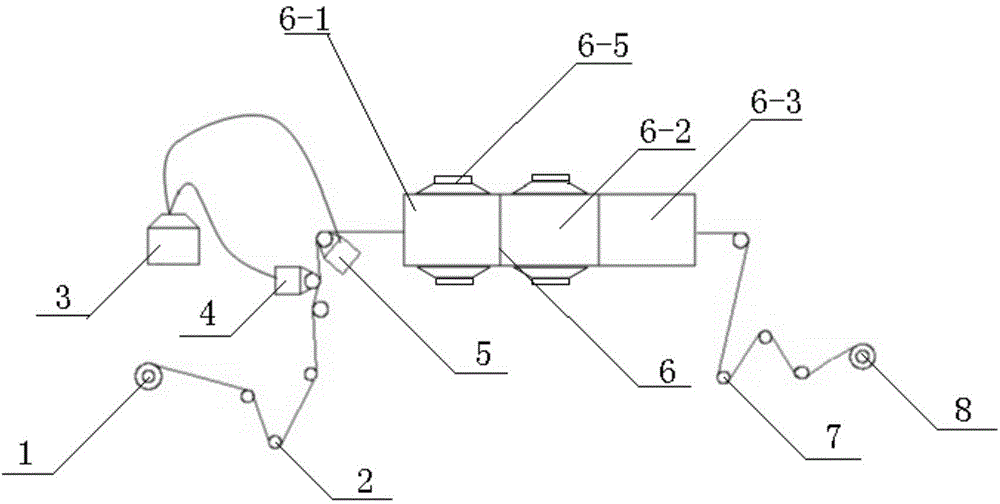
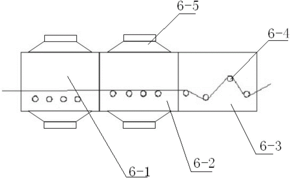
[0020] A diaphragm coating machine, comprising an unwinding roller 1, a traction roller 2, a feeding device 3, an upper station coating roller 4, a lower station coating roller 5, a horizontal oven group 6, a guide roller 7 and a winding Roller 8, the horizontal oven group 6 is formed by horizontally connecting three sections of separate ovens, and each section of separate ovens is provided with a transfer roller 6-4, wherein the first section of separate ovens 6-1 The conveying rollers 6-4 are arranged along the same horizontal plane, and the conveying rollers 6-4 in the second section of the separated oven 6-2 are arranged along the same horizontal plane, and their horizontal height is higher than that of the first section of the separated oven 6-2. - Each conveying roller 6-4 in 1, the height distance between each conveying roller 6-4 in the third section separated oven 6-3 and the bottom surface of the oven is different, so that the diaphragm to be coated is wound in an ang...


PUM


Abstract

The invention provides a diaphragm coating machine. The diaphragm coating machine comprises an unreeling roller, a gluing device, even groups of vertical type baking oven units, traction rollers, guide rollers, a flattening roller, a reeling roller and a main traction motor. The gluing device comprises a material liquid tank and a coating roller. The coating roller is arranged above the material liquid tank. The vertical type baking oven unit comprises a first vertical type baking oven and a second vertical type baking oven, and the ovens are arranged symmetrically. The unreeling roller, the coating roller, the traction rollers, the guide rollers, the flattening roller and the reeling roller are linked with the main traction motor. One side of the gluing device is provided with the unreeling roller. One of the vertical type baking oven units is arranged above the gluing device. The guide rollers are arranged above all the vertical type baking oven units. The guide rollers are arranged below the other one of the vertical type baking oven units, and are orderly transmission-connected to the flattening roller and the reeling roller. Through the diaphragm coating machine, the coating system realizes complete removal of a solvent in a diaphragm.

Description

technical field [0001] The invention relates to the field of manufacturing battery separators, in particular to a separator coating machine. Background technique [0002] The coating modification of lithium-ion battery diaphragm is a hot spot and a difficult point in the lithium battery industry at present. The hot point is that the heat resistance and mechanical strength of the lithium battery diaphragm itself are poor, which can no longer meet the needs of high specific energy density and large capacity battery systems. Therefore, improving its thermal and mechanical properties by coating modification has become an important direction for the development of diaphragm materials at home and abroad. The difficulty lies in: first, the thickness of the diaphragm is very thin, and the current main models used are generally within 20 microns, and the current mainstream diaphragm coating substrate has dropped to about 12 microns; second, because the diaphragm material is made by s...

Claims


Application Information

Patent Timeline
IPC IPC(8): B05C1/12B05C9/04B05C11/10B05C13/02B05D3/02
CPCB05C1/12B05C9/04B05C11/10B05C13/02B05D3/02
Inventor 闫义水
Owner TIANJIN LIHAO TECH DEV
Learn More