Workpiece welding clamp

A technology for welding fixtures and workpieces, which is applied in the direction of manufacturing tools, welding equipment, auxiliary welding equipment, etc., can solve the problems of high labor intensity and unguaranteed welding quality, and achieve the goal of ensuring welding accuracy, improving welding quality and welding efficiency Effect

Active Publication Date: 2015-05-06
SUZHOU AOGUAN ROBOTIZATION EQUIP
View PDF5 Cites 4 Cited by
  • Summary
  • Abstract
  • Description
  • Claims
  • Application Information

AI Technical Summary

Problems solved by technology

[0002] In the past, the construction machinery industry mostly used manual welding, which was labor-intensive and the welding quality could not be guaranteed.

Method used


Image

  • Workpiece welding clamp
  • Workpiece welding clamp

Examples


Embodiment Construction

[0014] The present invention will be further described below in conjunction with the accompanying drawings.

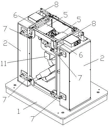
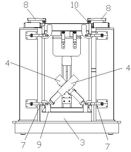
[0015] like figure 1 and figure 2 As shown, a workpiece welding fixture includes a base 1 and two columns 2 fixed on the base 1, a U-shaped seat 3 is also arranged on the base 1 between the two columns 2, and the two columns 2 are also provided with two mutually perpendicular lower inner braces 4 and two opposite upper inner braces 5, the angle between the lower inner braces 4 and the bottom surface of the U-shaped seat 3 is 45°, the tops of the two uprights 2 are provided with a limit strip 6 for limiting the workpiece and cooperating with the upper inner support member 5 . The workpiece is placed in the U-shaped seat 3, and the bottom of the workpiece is fixed by two lower inner support members 4, and the two sides of the workpiece are perpendicular to the bottom surface, and at the same time, two upper inner support members 5 are used to cooperate with the limit....


PUM


Abstract

The invention discloses a workpiece welding clamp which comprises a base and two stand columns fixed to the base. A U-shaped seat is further arranged on the part, between the two stand columns, of the base. Two lower inner spacer parts which are perpendicular to each other and two upper inner spacer parts which are oppositely arranged are arranged between the two stand columns, the included angles between the lower inner spacer parts and the bottom face of the U-shaped seat are 45 degrees, and limiting parts used for limiting workpieces and matched with the upper inner spacer parts are arranged on the tops of the two stand columns. The workpieces are comprehensively fixed through multiple clamping air cylinders in different stations, the welding precision can be ensured while a robot carries out welding, especially the weld penetration phenomenon of the workpieces with very thin materials can be avoided, and the welding quality and the welding efficiency are improved.

Description

technical field [0001] The invention relates to a workpiece welding fixture, which belongs to the technical field of robot welding. Background technique [0002] In the past, manual welding was mostly used in the construction machinery industry, which was labor-intensive and the welding quality could not be guaranteed. In recent years, a large number of welding robots have been used to replace ordinary workers for welding, which not only improves the quality, but also increases the output and reduces the cost. In the robot welding process, it is necessary to position the workpiece to be welded according to the required tooling, so that the robot can ensure the welding accuracy during the welding process and improve the welding quality. Especially for some workpieces with very thin material thickness, in order to avoid welding through during welding, the clamping requirements for fixtures are higher. Contents of the invention [0003] The technical problem to be solved by...

Claims


Application Information

Patent Timeline
Patent Type & Authority Applications(China)
IPC IPC(8): B23K37/04
CPCB23K37/0435
Inventor 洪峰潘冬亮
Owner SUZHOU AOGUAN ROBOTIZATION EQUIP
Why Eureka
Try Eureka