High-pressure group hole replacement grouting method and structure in karst region
A karst and regional technology, applied in infrastructure engineering, construction, etc., to achieve the effect of simple method, improved construction period, and guaranteed grouting quality
Active Publication Date: 2015-05-06
CHINA POWER CONSRTUCTION GRP GUIYANG SURVEY & DESIGN INST CO LTD
View PDF6 Cites 4 Cited by
- Summary
- Abstract
- Description
- Claims
- Application Information
AI Technical Summary
Problems solved by technology
[0006] The purpose of the present invention is to solve the problem of engineering anti-seepage grouting treatment in karst karst areas in the prior art, and to provide a high-pressure group hole replacement grouting method in karst areas
Method used
View moreImage
Smart ImageViewing Examples
Examples
Embodiment 1
[0030] The filling-type karst cave in the curtain grouting test area of the lower flat hole of a hydropower station is mainly filled with clay, which is prone to the phenomenon of porous interconnection (cross-flow, cross-flow of grout), and the porous holes cannot meet the design requirements after repeated refilling. After the treatment is completed, the inspection through the grouting inspection hole can meet the design requirements.
Login to View More PUM
 Abstract
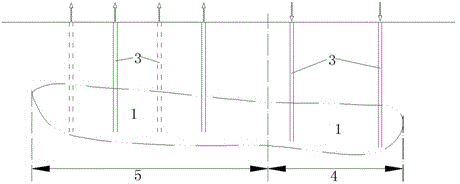
The invention discloses a high-pressure group hole replacement grouting method and structure in a karst region. A grouting gallery or an adit (2) is arranged above a karst cave area (1), a drilling hole (3) is distributed in the grouting gallery or the adit (2) towards the karst cave area (1), the lower end of the drilling hole (3) is located in the karst cave area (1), and the range where the drilling hole (3) is located is divided into a replacement inlet area (4) and a replacement outlet area (5); sand-mixed cement mortar with the mass ratio of 0.5:1 is injected into the drilling hole (3) in the replacement inlet area (4) through high pressure, filler of the karst cave is extruded out of the drilling hole (3) of the replacement outlet area (5) fully or partially, and then a common cement grouting method is adopted for grouting 24-36 hours later after condensation. The high-pressure group hole replacement grouting method and structure in the karst region realize grouting of medium and small filling-type karst cave and other geological flaw sections in the karst region, and have the advantages of being simple, capable of largely shortening the construction period, low in expense, obvious in effect, capable of guaranteeing grouting quality, and the like.
Description
technical field [0001] The invention relates to a karst karst geological treatment method, in particular to a grouting method and a structure for replacing high-pressure group holes in a karst area. Background technique [0002] Karst terrain refers to the general term for the surface and underground forms formed by the dissolution of soluble rocks by water with dissolution power. The main action of water is dissolution, which also includes mechanical erosion processes such as flowing water erosion, shallow erosion, and subsidence. [0003] In the construction of water conservancy and hydropower projects in karst areas, karst seepage of reservoirs is one of the main engineering problems. The selection of appropriate and effective anti-seepage solutions is related to whether the reservoir can store water normally. At present, the anti-seepage grouting treatment project in karst area is mainly cement grouting. In the process of grouting construction, large and small caves fi...
Claims
Login to View More Application Information
Patent Timeline
 IPC IPC(8): E02D19/16E02D15/04
CPCE02D15/02E02D19/16E02D2250/003
Inventor 屈昌华郭维祥余波朱代强昝廷东
Owner CHINA POWER CONSRTUCTION GRP GUIYANG SURVEY & DESIGN INST CO LTD
Features
- R&D
- Intellectual Property
- Life Sciences
- Materials
- Tech Scout
- Unparalleled Data Quality
- Higher Quality Content
- 60% Fewer Hallucinations
Learn More Browse by: Latest US Patents, China's latest patents, Technical Efficacy Thesaurus, Application Domain, Technology Topic, Popular Technical Reports.
© 2025 PatSnap. All rights reserved.Legal|Privacy policy|Modern Slavery Act Transparency Statement|Sitemap|About US| Contact US: help@patsnap.com


