A method for installing the cutter beam long axis hole cutter bracket of cutter suction dredger

The technology of a cutter suction dredger and its installation method is applied in the direction of mechanically driven excavators/dredgers, etc., which can solve the problems of long production cycle, difficulty in meeting high efficiency requirements, and low efficiency, so as to reduce processing difficulty, The effect of reducing work complexity and coordination difficulty and improving work efficiency

Active Publication Date: 2017-10-27
GUANGZHOU WENCHONG SHIPYARD CO LTD
View PDF5 Cites 0 Cited by
  • Summary
  • Abstract
  • Description
  • Claims
  • Application Information

AI Technical Summary

Problems solved by technology

However, this method has a long production cycle and low efficiency, and it is difficult to meet the modern high-efficiency requirements

Method used


Image

  • A method for installing the cutter beam long axis hole cutter bracket of cutter suction dredger
  • A method for installing the cutter beam long axis hole cutter bracket of cutter suction dredger
  • A method for installing the cutter beam long axis hole cutter bracket of cutter suction dredger

Examples


Embodiment Construction

[0015] A method for installing a cutter beam long axis hole cutter support of a cutter suction dredger, comprising the following steps:

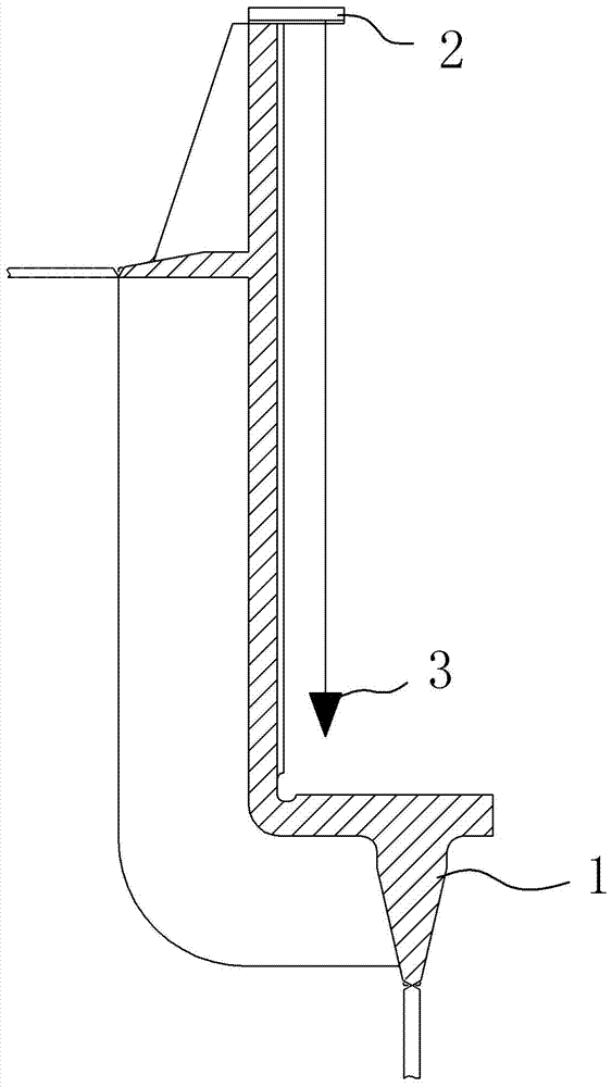
[0016] A. Mark the twist point seat, and draw the horizontal centerline, longitudinal centerline and horizontal positioning line respectively;

[0017] B. Carry out lines on the general section of the hull, draw horizontal lines, rib position lines and transverse positioning lines respectively;

[0018] C. Hoist the hinge point seat, hoist the hinge point seat on the general section of the hull for positioning, and align with the horizontal line, rib position line and transverse positioning line respectively;

[0019] D. Weld the twist point seat to the general section of the hull;

[0020] E. After installing the twist point seat on the hull, install the twist shaft and the twist cover.

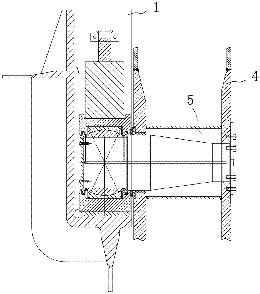
[0021] Such as figure 1 As shown, there is a long axis hole 5 on the reamer beam 4, and the reaming point seat 1 is installed at the long axis hole of ...


PUM


Abstract

A method for installing the long axis hole winch support of the cutter beam of a cutter suction dredger, respectively draw lines on the winch point seat and the general section of the hull, and then align and install the two lines, and control the joints during the installation process. Verticality, when welding the twist point seat, carry out symmetrical welding on both sides. After the twist point seat is installed on the hull, install the twist shaft and the twist cover. The setting of the reaming point seat can prefabricate the reamer beam, thereby avoiding the disadvantages of on-site boring installation, which can effectively shorten the production cycle and improve work efficiency; at the same time, it greatly reduces the need for auxiliary tooling and reduces the processing difficulty. There is no need to use dummy shafts for auxiliary processing, which reduces processing difficulty and production costs.

Description

technical field [0001] The invention relates to a cutter suction dredger, in particular to a method for installing a cutter beam long axis hole cutter bracket of a cutter suction dredger. Background technique [0002] Cutter suction dredger is a kind of static dredger, which is widely used in port, waterway dredging and reclamation projects. The dredger is equipped with a reamer as an excavating tool, so that the soil is sucked after cutting; and the beam on which the reamer is installed is the reamer beam. [0003] In order to ensure the installation accuracy, the current cutter suction dredger, the shaft hole of the cutter beam needs to be produced on the production site. In addition, special tooling tools and auxiliary cooperation with dummy shafts are required to complete the installation of the cutter suction dredger. However, this method has a long production cycle and low efficiency, and it is difficult to meet the modern high-efficiency requirements. Contents of ...

Claims


Application Information

Patent Timeline
Patent Type & Authority Patents(China)
IPC IPC(8): E02F3/90
Inventor 张鹏程肖淑琪陈炽平申都督李法铭
Owner GUANGZHOU WENCHONG SHIPYARD CO LTD
Why Eureka
Try Eureka