Sand removing device applicable to high-pressure and high-yield gas well

A high-yield, gas well technology, applied in the direction of combined devices, wellbore/well components, production fluids, etc., can solve the problems of poor site adaptability, difficult management of desanding devices, high investment costs, etc., and achieve the effect of preventing erosion and damage

Active Publication Date: 2015-05-06
PETROCHINA CO LTD
View PDF6 Cites 14 Cited by
  • Summary
  • Abstract
  • Description
  • Claims
  • Application Information

AI Technical Summary

Problems solved by technology

[0005] According to the characteristics of the above three commonly used sand production devices, gas wells with high pressure, high production and high sand volume need to consider two or three types of sand control devices for combined sand removal, which leads to high investment costs and difficulty in daily operation and management of multiple sand removal devices , poor site adaptability

Method used


Image

  • Sand removing device applicable to high-pressure and high-yield gas well
  • Sand removing device applicable to high-pressure and high-yield gas well
  • Sand removing device applicable to high-pressure and high-yield gas well

Examples


Embodiment 1

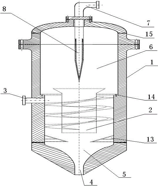
[0028] Such as figure 1 As shown in the structural diagram of the desanding device for the high-pressure and high-yield gas well, it at least includes a pressure vessel 1 in a vertical structure, a cyclone separator 2 is arranged under the pressure vessel 1, and an air inlet 3 is located on the side of the cyclone separator 2 At the side wall of the square pressure vessel 1, the bottom of the pressure vessel 1 is the sand discharge port 4, the sand storage area 5 is between the bottom of the cyclone separator 2 and the sand discharge port 4, and the inner space of the pressure vessel 1 above the cyclone separator 2 It is a gravity settling area 6 , the top of the pressure vessel 1 has an air outlet 7 , and a filter cartridge 8 is connected below the air outlet 7 , and the filter cartridge 8 extends into the gravity settling area 6 .

[0029] The gas inlet 3 is arranged at the side wall of the pressure vessel 1 along the tangential direction.

[0030] The pressure vessel 1 of ...

Embodiment 2

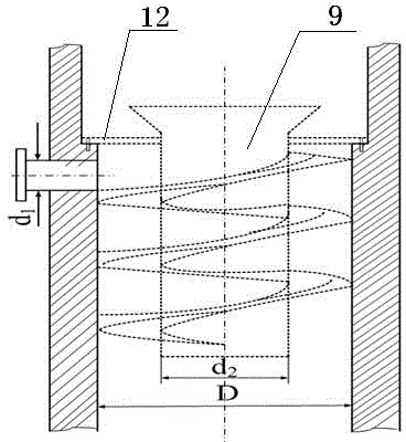
[0034] Such as figure 2 As shown in the structural schematic diagram of the cyclone separator, the cyclone separator in the pressure vessel 1 is composed of an air riser 9, a horizontal vane 10 and a vertical vane 11.

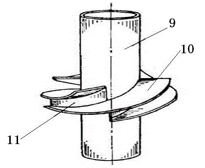
[0035] The upper part of the gas riser 9 is connected to the inner wall of the pressure vessel 1 above the air inlet 3 through a fixed partition 12, and the horizontal blades 10 are fixed in a spiral shape on the outer wall of the gas riser 9 below the fixed partition 12, and the spirally distributed horizontal blades 10 The inner diameter is fixedly connected with the riser pipe 9, and the outer diameter of two adjacent horizontal blades 10 is connected with a vertical blade 11, and the vertical blade 11 seals the space between the adjacent two horizontal blades 10 as an airtight space, see image 3 A helical channel is formed outside the air riser 9, the upper port of the helical channel is located at the air inlet 3 of the pressure vessel 1, and the lower p...

Embodiment 3

[0045] On the basis of Embodiment 2, there is a boss 14 on the inner wall above the air inlet 3 of the pressure vessel 1 in this embodiment, and the outer edge of the fixed partition 12 is detachably connected to the boss 14 by bolts, and the fixed partition 12 The inner edge is fixedly connected with the upper outer wall of the gas riser 9, and the upper port of the gas riser 9 above the fixed partition 12 is a bell mouth.

[0046] The top of the pressure vessel 1 is connected with a container upper cover 15 through a flange. The inner diameter of the container upper cover 15 is consistent with the inner diameter of the upper gravity settlement area 6 of the pressure vessel 1. The gas outlet 7 is located at the center of the container upper cover 15 .

[0047] The fixed partition 12 not only divides the pressure vessel 1 into upper and lower parts, the two parts are the cyclone separation area and the gravity sedimentation area 6, the two areas do not interfere with each other...


PUM


Abstract

The invention relates to the field of sand removal of a gas well, in particular to a sand removing device applicable to a high-pressure and high-yield gas well. The inside of a pressure container of the sand removing device mainly consists of four parts including a sand storage region, a cyclone separator, a gravity settling region and a filter tube, wherein the cyclone separator carries out first-stage sand removal on sand-containing natural gas entering the device, the natural gas subjected to the first-stage sand removal is subjected to second-stage sand removal through receiving the gravity effect after entering a gravity settling region, the natural gas is exhausted from a gas outlet after being subjected to third-stage sand removal via the filtering tube, solid phase sand is fully separated after the sand-containing natural gas is subjected to first-stage, second-stage and third-stage sand remove, and the flushing and the damage of the sand on subsequent pipelines and equipment can be effectively prevented.

Description

technical field [0001] The invention relates to the field of sand removal for gas wells, in particular to a sand removal device suitable for high-pressure and high-yield gas wells. Background technique [0002] The backflow of proppant in ancient fracturing gas wells in southeast Jiangsu is a common phenomenon, especially the backflow of proppant in high pressure and high production gas wells is more serious. Sand production in fracturing gas wells will lead to a decrease in the conductivity of artificial fractures. , testing, production seeking stages and post-compression collection and transmission bring great potential safety hazards. [0003] When the gas production of gas wells is greater than 120,000 m3 / day, the pressure is higher than 20 MPa, and the particle size of sand and gravel is small, several commonly used single-set sand removal devices cannot meet the on-site sand removal requirements. [0004] For example, the cyclone desander is suitable for gas wells wit...

Claims


Application Information

Patent Timeline
Patent Type & Authority Applications(China)
IPC IPC(8): E21B43/34B01D50/00
CPCE21B43/34B01D50/10
Inventor 张振文李泉于东华尚万宁党晓峰陈志军李柏鹏吕玉海张腾
Owner PETROCHINA CO LTD
Why Eureka
Try Eureka