Variable Displacement Swash Plate Compressor

A swash plate type, variable displacement technology, applied in the field of air-conditioning compressors, can solve problems such as affecting the operation of the compressor, severe friction, noise, parts damage, etc., and achieve the effects of simple assembly, collision prevention, and enhanced reliability.

Inactive Publication Date: 2017-12-08
SANDEN HUAYU AUTOMOTIVE AIR CONDITIONING CO LTD
View PDF12 Cites 0 Cited by
  • Summary
  • Abstract
  • Description
  • Claims
  • Application Information

AI Technical Summary

Problems solved by technology

[0005] The shell of the bearing 52 is a stationary part fixed on the cylinder block, and the circlip 26 is fixed on the main shaft 18 and rotates at high speed. When the two collide, violent friction and noise will be generated. In serious cases, the two parts will be damaged and affect the compressor operation

Method used


Image

  • Variable Displacement Swash Plate Compressor
  • Variable Displacement Swash Plate Compressor
  • Variable Displacement Swash Plate Compressor

Examples


Embodiment Construction

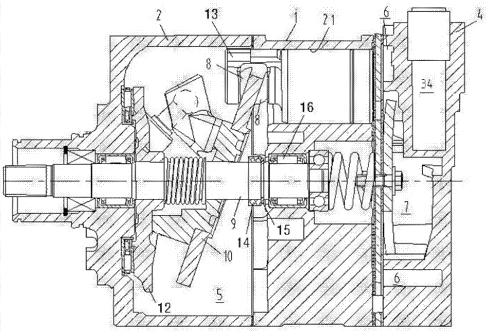
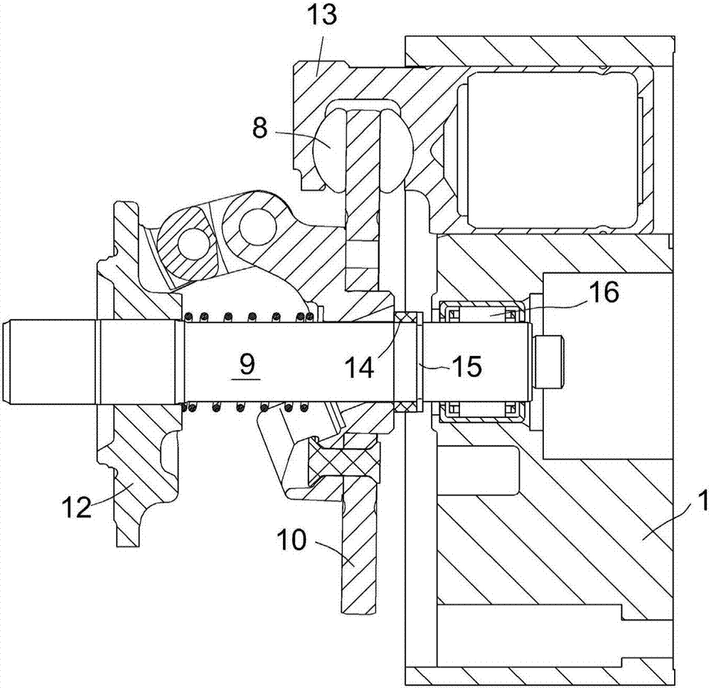
[0016] The compressor used in the refrigeration cycle of the car air conditioner is driven by the engine, and the speed of the engine changes according to the motion state of the car. The variable capacity compressor with variable refrigerant displacement can obtain sufficient cooling capacity when the engine is idling. Such as figure 1 As shown, in the variable capacity compressor, the shell of the swash plate compressor is assembled from the front cylinder head 2, the cylinder block 1 and the rear cover 4, forming the crankshaft chamber 5, the suction chamber 6, and the exhaust chamber 7 and a plurality of cylinder bores 21. When the compressor is working, the rear end of the main shaft 9 is supported by the bearing 16 in the middle hole of the cylinder body. Driven by the engine, the main shaft 9 drives the drive plate 12 mounted on it and the swash plate 10 hinged with the drive plate 12 to rotate simultaneously. The swash plate 10 forms an inclination angle with the ma...


PUM


Abstract

The purpose of the present invention is to provide a variable displacement swash plate compressor, which can make the assembly of the compressor easier. The variable-displacement swash plate compressor for achieving the above purpose includes a rotating main shaft, a swash plate driven by the main shaft to rotate, a reciprocating piston driven by the swash plate, a bearing on the main shaft to support the rotation of the main shaft in the cylinder, The elastic member arranged on the main shaft between the bearing and the swash plate and the stopper that restricts the movement of the elastic member toward the bearing are characterized in that the elastic member includes a rubber washer, and the material of the rubber washer is selected from half One of the general-purpose synthetic rubbers.

Description

technical field [0001] The invention relates to an air conditioner compressor, in particular to a variable displacement swash plate compressor. Background technique [0002] The U.S. patent No. US6250891 proposes a variable displacement compressor, such as image 3 As shown, the front side of the swash plate 20 has a spring 25 that pushes the swash plate to reduce the angle, and the rear side has a return spring 27 that pushes the swash plate to increase the angle, and a snap ring 26 is used to limit the rear end 271 of the return spring 27 . The free length of the return spring 27 is less than the distance between the lower swash plate 20 and the retaining spring 26 at the maximum angle. The rear end of the main shaft 18 is rotatably supported in the cylinder block 11 by a bearing 52 . [0003] Since supporting rings need to be set up and down, plus the required number of effective turns, the free length of the helical return spring 27 in the variable displacement compres...

Claims


Application Information

Patent Timeline
Patent Type & Authority Patents(China)
IPC IPC(8): F04B27/12F04B39/00
Inventor 陈思赟马文彬巢勇程宇超李琳季赟华
Owner SANDEN HUAYU AUTOMOTIVE AIR CONDITIONING CO LTD
Why Eureka
Try Eureka