Ceramic cooling roll

A cooling roller, ceramic technology, applied in sustainable manufacturing/processing, heat exchange equipment, climate sustainability, etc., to achieve the effect of reducing water consumption, improving wear resistance, and increasing service life

Inactive Publication Date: 2015-05-06
WEIHAI FENGTAI NEW MATERIAL SCI & TECH
View PDF5 Cites 8 Cited by
  • Summary
  • Abstract
  • Description
  • Claims
  • Application Information

AI Technical Summary

Problems solved by technology

[0003] In order to solve the technical problems existing in the prior art, the present invention provides a ceramic cooling roll, and at the same time, the structure in the roll body is improved to solve the existing technical problems

Method used


Image

  • Ceramic cooling roll
  • Ceramic cooling roll
  • Ceramic cooling roll

Examples


Embodiment 1

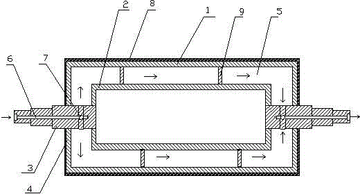
[0016] as attached figure 1 As shown, the ceramic cooling roller includes an outer roller 1 and an inner cylinder roller 2 arranged coaxially. The left and right ends of the inner cylinder roller are respectively provided with shaft heads 3, and the left and right shaft heads pass through the ends of the outer roller respectively. The sealing plate 4 forms a water cavity 5 between the outer roller and the inner cylinder roller, and a counterbore 6 parallel to the shaft head is provided at the axial center of the left and right shaft head ends, and the counterbore 6 is arranged toward the shaft head. The inside of the head extends to between the end of the outer roller and the end of the liner roller, and a number of through holes 7 that communicate with the counterbore are radially provided on the wall of the shaft head in this area.

[0017] When in use, the left and right shaft heads 3 are connected to the rotary seal joints respectively, and the water with pressure enters ...

Embodiment 2

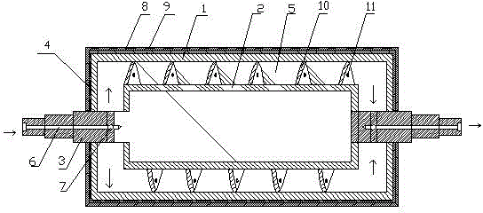
[0022] The ceramic cooling roller provided in Example 1 adds a ceramic layer 8 on the surface of the outer roller 1 to improve the corrosion resistance, wear resistance and anti-sticking performance of the cooling roller. The surface of the roller 1 has poor adhesion, and when used at high temperature for a long time, the ceramic layer 8 will easily form cracks and occur in broken and separated, which reduces the service life of the cooling roller.

[0023] To solve this problem, the attached figure 2 As shown, in this embodiment, when making the ceramic layer 8, the surface of the outer roller 1 after cleaning and drying is now sprayed with a layer of nickel-aluminum alloy layer 9 by laser, and then sent into a drying room for curing and drying, and then coated with nickel-aluminum alloy A ceramic layer 8 is sprayed on the surface of the alloy layer 9 . The thickness of the nickel-aluminum alloy layer 9 is controlled to be between 10-20 wires. Since nickel-aluminum alloy h...


PUM

PropertyMeasurementUnit
thicknessaaaaaaaaaa

Abstract

The invention relates to a cooling device. In order to solve the technical problem in the prior art, the invention provides a ceramic cooling roll. The ceramic cooling roll comprises an outer roller and a liner roller which are coaxially arranged, wherein the left end and the right end of the liner roller are respectively provided with a shaft head; the left shaft head and the right shaft head penetrate through an end-part sealing plate of the outer roller respectively; a water cavity is formed between the outer roller and the liner roller; the axis positions of the end parts of the left shaft head and the right shaft head are internally provided with sinking holes parallel to the shaft heads; and the sinking holes extend to the inner parts of the shaft heads to be between the end part of the outer roller and the end part of the liner roller, and a plurality of through holes communicated with the sinking holes are radially formed in the shaft head walls of the area. The ceramic cooling roll is characterized in that a ceramic layer is arranged on the surface of the outer roller. The ceramic cooling roll provided by the invention is reasonable in structure and simple in manufacture and can be widely applied to linkage production line equipment of papermaking, plastics and rubber and the like.

Description

technical field [0001] The invention relates to a cooling device, in particular to a ceramic cooling roller. Background technique [0002] Cooling rolls are mainly used in papermaking, plastic, rubber and other linkage production line equipment, mainly through the circulation of water under a certain pressure in the roll, and maintain a constant cooling temperature so that paper, plastic sheets, film materials and rubber sheets can be cooled quickly. When the temperature is lowered to the temperature required by the process, its main performance should achieve anti-corrosion, anti-sticking, high heat conduction efficiency, and wear resistance. Most of the cooling rolls used in traditional equipment are solved by chrome-plated rolls, but the chrome-plated rolls only solve the problems of anti-corrosion and heat conduction efficiency, and their anti-sticking and wear resistance are poor. With the development of technology, Teflon rollers are used to replace chrome-plated roll...

Claims


Application Information

Patent Timeline
Patent Type & Authority Applications(China)
IPC IPC(8): F16C13/00F28F5/02
CPCY02P80/10
Inventor 钱国峰刘海庆
Owner WEIHAI FENGTAI NEW MATERIAL SCI & TECH
Why Eureka
Try Eureka