Whole-process variable displacement oil pump for pressure control

A pressure control and displacement machine technology, which is applied in the directions of lubricating oil control valve, lubricating pump, mechanical equipment, etc., can solve the problems of incapable of realizing variable displacement in the whole process, complicated pressure adjustment, and troublesome adjustment. A responsive, responsive effect

Inactive Publication Date: 2015-05-06
NINGBO SHENGLONG AUTOMOTIVE POWERTRAIN SYSTEM CO LTD
View PDF7 Cites 3 Cited by
  • Summary
  • Abstract
  • Description
  • Claims
  • Application Information

AI Technical Summary

Problems solved by technology

[0005] 1) In the above two pressure level controls provided by the pump, within the engine speed range of 0 ~ 3500RPM, the position of the slider and the flow and pressure output by the pump are the pressure functions in the first chamber and the second chamber. In other words, the pressure in the first and second chambers is proportional to the speed of the pump; over the range of engine speeds greater than 3500 RPM, the position of the slider is determined by the pressurization level of the second chamber that communicates with the valve Yes, this is a passive mode; therefore, in the entire speed change of the engine, it is necessary to switch from the first pressure control to the second pressure control, and it is too complicated to realize the pressure regulation;
[0006] 2) The valve involved in the above pump is a pressure regulating valve, usually there are two types, one is a manual regulating valve, but this kind of manual pressure regulating valve is very inconvenient to use, especially not suitable for full-range variable displacement The other is a solenoid valve, but the solenoid valve usually changes the flow direction of the fluid according to the on-off of the current, so as to increase or decrease the pressure in the second chamber, and the adjustment of the pressure still needs to be set in advance. The change of flow rate and pressure can be achieved only by the speed of rotation. It is also very troublesome to adjust, and it is impossible to realize the need of variable displacement throughout the process.

Method used


Image

  • Whole-process variable displacement oil pump for pressure control
  • Whole-process variable displacement oil pump for pressure control
  • Whole-process variable displacement oil pump for pressure control

Examples


Embodiment Construction

[0021] The present invention will be described in further detail below in conjunction with the accompanying drawings and specific embodiments.

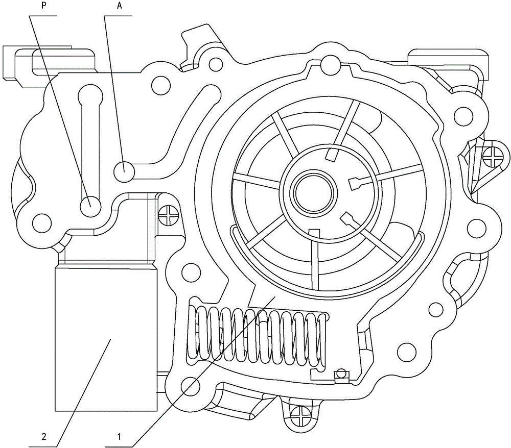
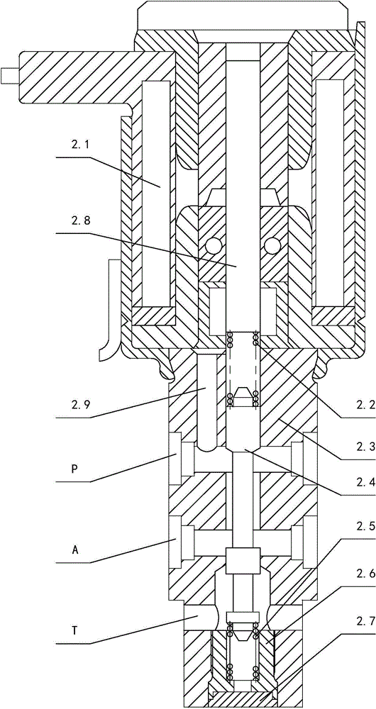
[0022] Depend on Figure 1 to Figure 4 It can be seen from the schematic structural diagram of the pressure-controlled full-range variable displacement oil pump of the present invention that it includes a pump main body 1 and a solenoid valve 2. The pump main body 1 is provided with a discharge reduction cavity and an increase discharge cavity. The valve 2 is mounted on the pump body 1 . The solenoid valve 2 includes an electromagnet assembly 2.1, a first spring 2.2, a second spring 2.5, a valve body 2.3 and a valve core 2.4, the valve body 2.3 is fixedly connected in the pump main body 1, and the upper end of the valve body 2.3 is connected to the electromagnet assembly 2.1 Fixed connection. The upper end of the spool 2.4 is connected with the armature 2.8 in the electromagnet assembly 2.1 through the first spring 2.2, the spool 2....


PUM


Abstract

The invention discloses a whole-process variable displacement oil pump for pressure control, which comprises a pump main body and a solenoid valve, wherein the solenoid valve comprises an electromagnet component, a first spring, a second spring, a valve body and a valve core, wherein the upper end of the valve core is connected with an armature in the electromagnet component through the first spring; the lower end of the valve core is connected with the valve body through the second spring; a working oil port of the solenoid valve is communicated with an emission reduction chamber in the pump main body; an oil outlet of the pump main body is communicated with an oil inlet of the solenoid valve; the working oil port is communicated with an upper chamber of the valve core. After the structure is adopted, the variable of the displacement of the whole oil pump can be controlled in the whole process and can be realized by only adjusting an input current of the solenoid valve, the operation is simple and convenient and the adjusting is accurate.

Description

technical field [0001] The invention relates to the technical field of oil pumps, in particular to a pressure-controlled full range variable displacement oil pump. Background technique [0002] When the automobile engine is working, each moving part acts on another part with a certain force, and high-speed relative motion occurs. With relative motion, friction will inevitably occur on the surface of the parts, thereby accelerating wear. Therefore, in order to reduce wear, reduce frictional resistance, and prolong service life, there must be a lubrication system on the engine. The main components of the lubrication system are various equipment such as an oil pump. The function of the oil pump is to increase the oil to a certain pressure and then forcefully send it to the moving surface of each part of the engine. It generally includes a pump cover and a pump body. It is connected with the pump body by screws, and the pump body is equipped with an inner rotor, an outer rotor,...

Claims


Application Information

Patent Timeline
Patent Type & Authority Applications(China)
IPC IPC(8): F16N23/00F16N13/20
Inventor 项鑫罗玉龙周培良邹娟俞黎明李阳星廖小华
Owner NINGBO SHENGLONG AUTOMOTIVE POWERTRAIN SYSTEM CO LTD
Why Eureka
Try Eureka