

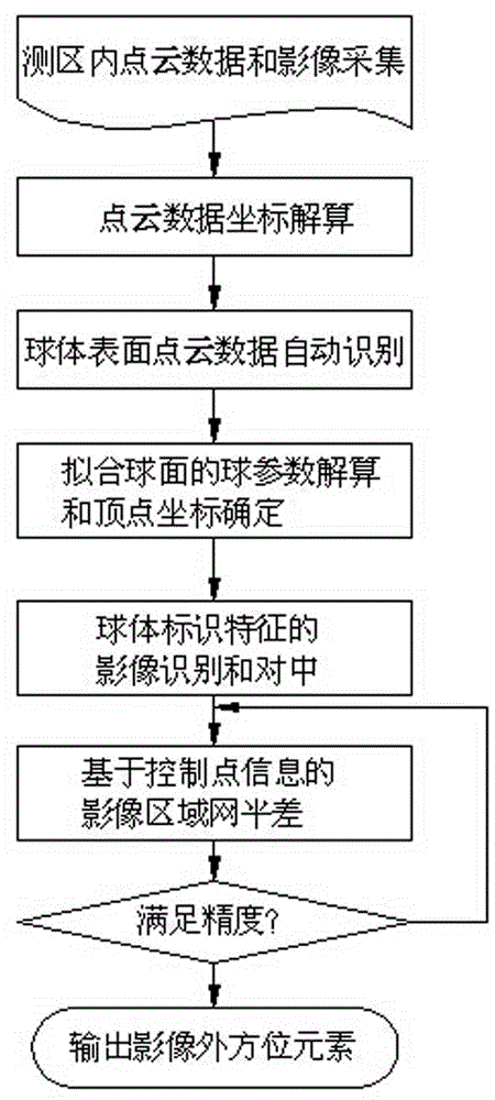
Movable target sphere oriented onboard LiDAR point cloud and image united rectification method
A technology of moving targets and target balls, applied in the field of measurement, can solve problems such as inaccurate line positioning, high-precision registration of laser point clouds and spectral images, etc., to improve modeling efficiency, reduce control information interaction workload, and facilitate The effect of quasi-precision
- Summary
- Abstract
- Description
- Claims
- Application Information
AI Technical Summary
Problems solved by technology
Method used
Image

Examples
Embodiment 1
[0076] Embodiment one : Point cloud image registration experiment of airborne lidar to survey area.
[0077] Survey area: Covering an area of 4 square kilometers, the terrain is undulating; there are dozens of known ground control points evenly distributed within the range.
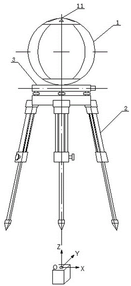
[0078] Target ball device: the radius of the upper sphere is 0.320m. It is erected at known ground control points, and the apex of the sphere, the center of the sphere and the ground control points are on the same plumb line; one is installed at each of the four corners of the survey area, and they are respectively placed at known ground control points. At the same time, three are set in the center of the survey area as accuracy checkpoints.
[0079] Flight and parameters: large unmanned helicopter, relative altitude 250m;
[0080] Parallel flight, 2 strips to and fro, with an average scanning width of 550m;
[0081] Airborne equipment: 1. LiDAR system. It is a laser measuring device. Its emissio...
Embodiment 2
[0098] Embodiment two: This embodiment is aimed at the point cloud and image registration test of the airborne lidar survey area in another mountainous zone.
[0099] The specific steps and processes of this embodiment are basically the same as those of Embodiment 1, and the differences will be described in detail below.
[0100] The status of the survey area is quite different from that in Embodiment 1, but this difference does not have any impact on the registration method of the present invention; the arrangement and structural changes of the target ball device can be selected according to the situation, but it does not affect the registration method of the present invention. methods; neither are described in detail here. The laser scanning point spacing used in this embodiment is 0.180m. After the point cloud data is collected by scanning and the area image is collected by the digital camera, the point cloud data is uploaded, solved and stored in the computer; the real-...
PUM
 Abstract
Description
Claims
Application Information