
Establishing and maintaining focus in segmented-optic telescopes

a segmented-optic telescope and telescope technology, applied in the field of multi-aperture interferometric optical systems, to achieve the effect of better behavior

Inactive Publication Date: 2009-02-26
VENTURE ASTRA
View PDF25 Cites 21 Cited by
  • Summary
  • Abstract
  • Description
  • Claims
  • Application Information

AI Technical Summary

Problems solved by technology

Stated in simpler terms, the disclosure does not implement an attempt to beam-combine a singular image onto an electronic sensor or light sensitive film under the expensive assumption that one has physically forced a large structure to maintain nanometer-scale intra-positional accuracies.

Method used


Image

  • Establishing and maintaining focus in segmented-optic telescopes
  • Establishing and maintaining focus in segmented-optic telescopes
  • Establishing and maintaining focus in segmented-optic telescopes

Examples


Embodiment Construction

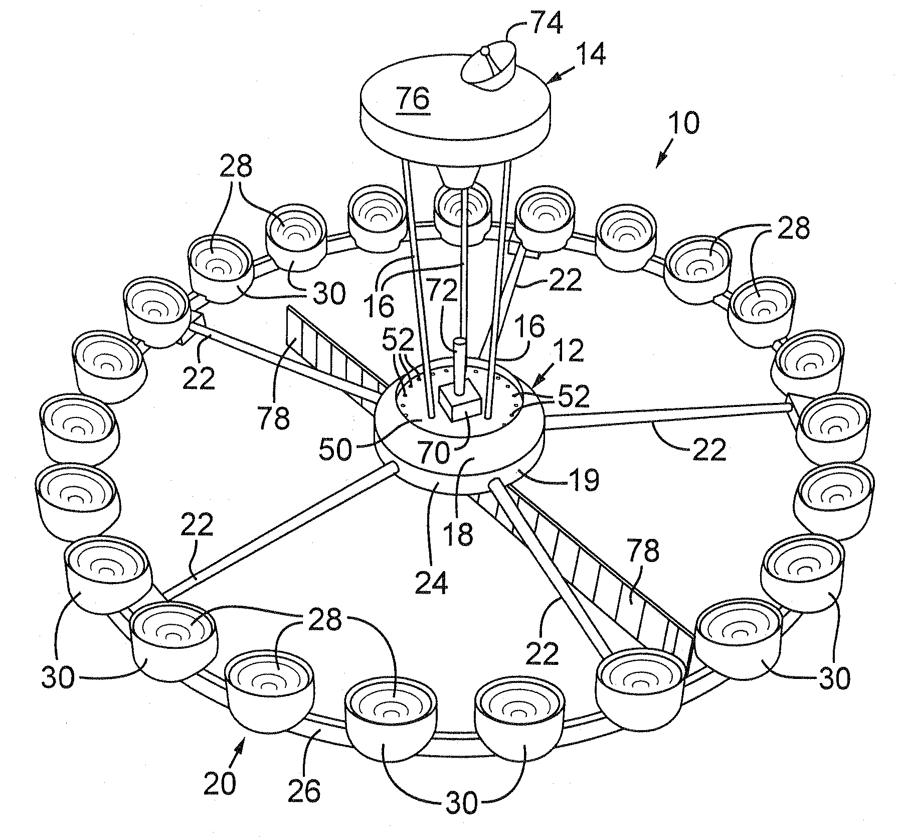
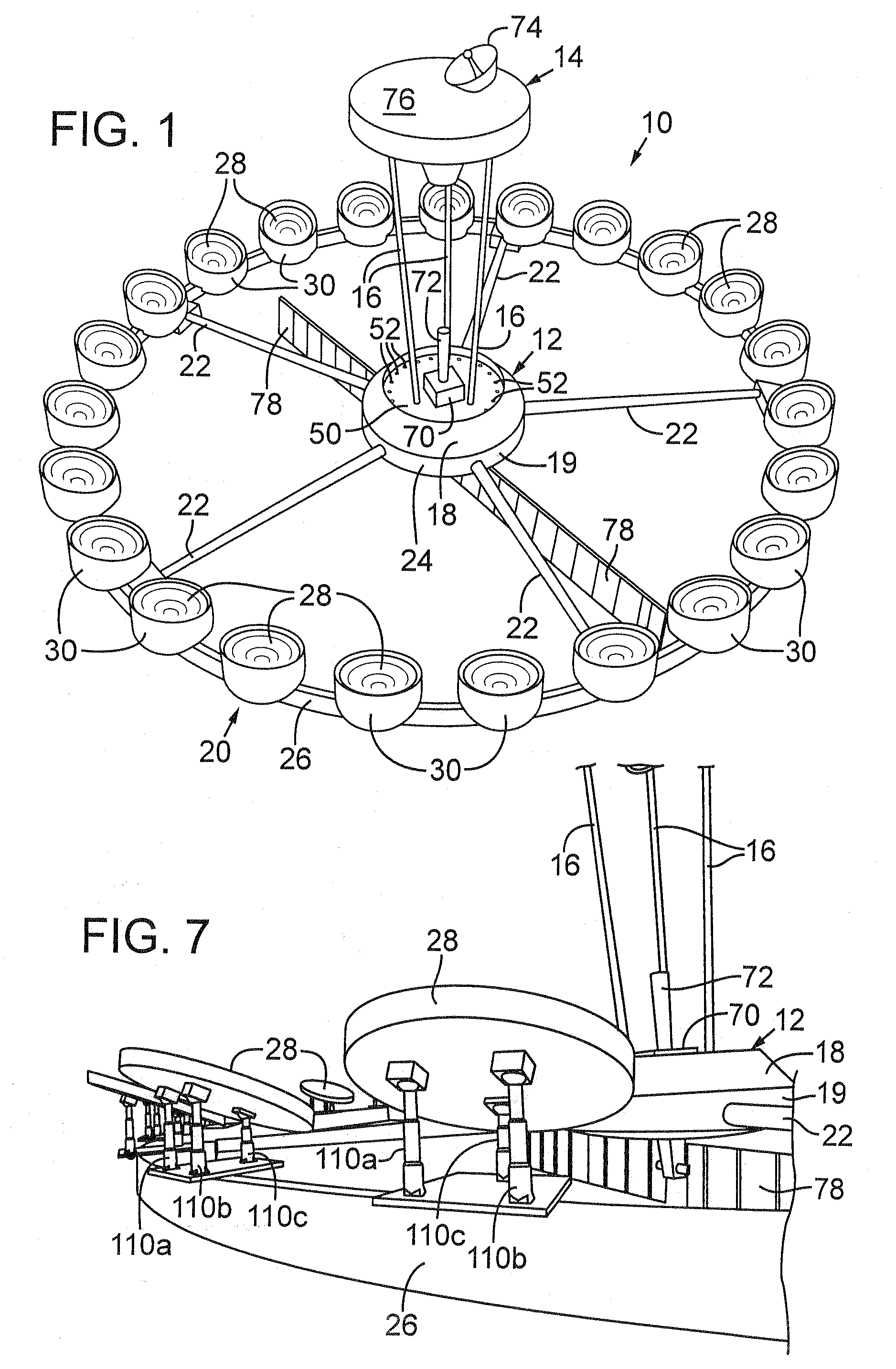
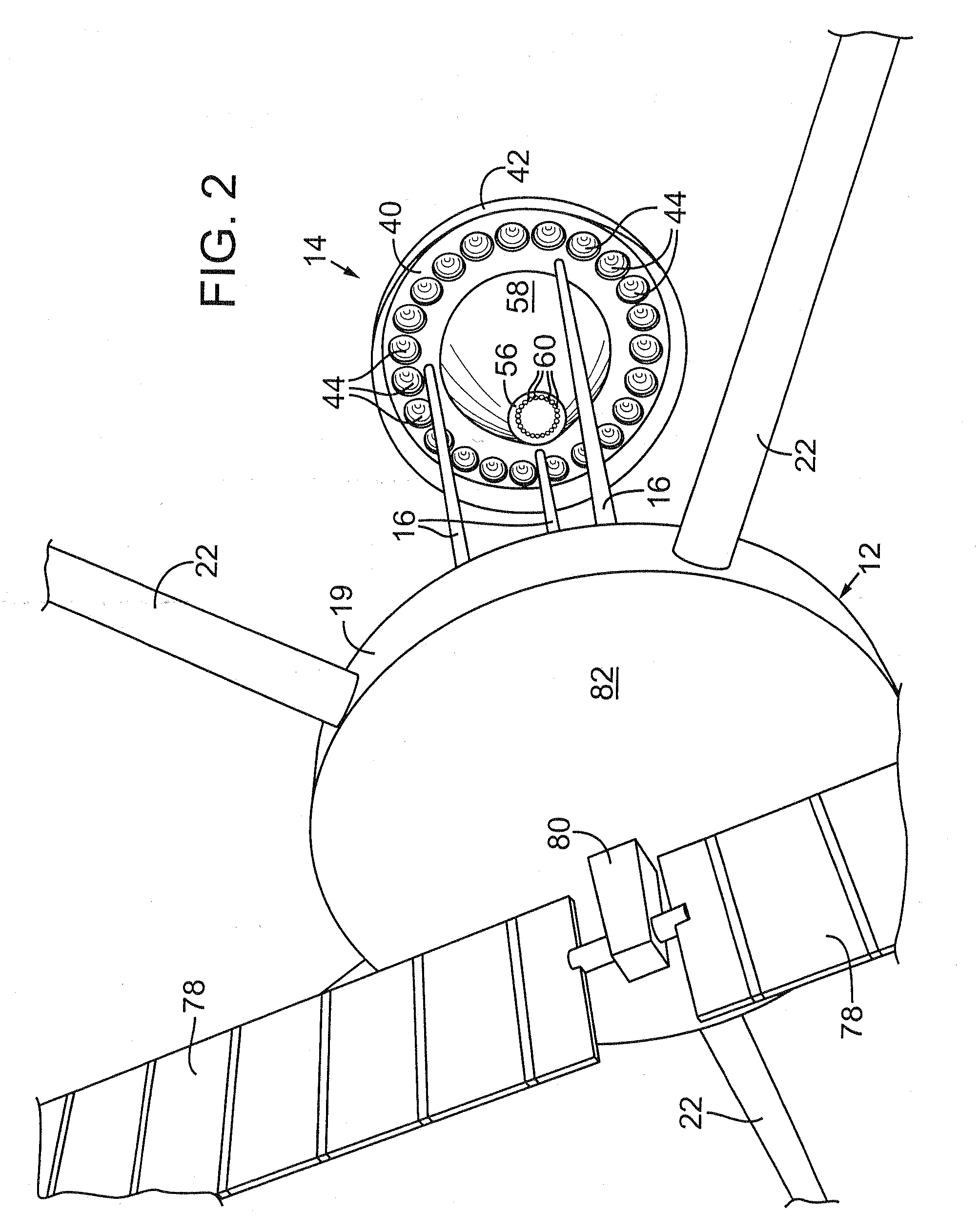
[0054]FIGS. 1 and 2 show an isometric view and an enlarged, fragmentary rearward view, respectively, of a preferred embodiment of an orbiting multi-aperture interferometric optical system 10 constructed in accordance with one embodiment. With reference to FIGS. 1 and 2, optical system 10 is composed of a main body in the form of a central hub 12 and a secondary assembly in the form of a plate structure 14 spaced apart from each other by connection to the opposite ends of three cylindrical columns 16. Central hub 12 is composed of two separate cylindrical structures 18 and 19, the larger structure 18 containing most of the satellite equipment and the smaller structure 19 providing an anchor for a primary mirror structure 20 and containing a multi-spectral primary optical detector. Four mirror ring structures, two each connected to central hub 12 and plate structure 14, direct incoming light to the multi-spectral primary optical detector positioned at a detector plane on central hub 1...


PUM


Abstract

A multi-aperture interferometric optical system collects light propagating from a source of light and develops overlapping diffraction patterns on an optical detector that produces output signals for processing to automatically focus the optical system and form an image corresponding to the diffraction patterns. A preferred embodiment of the invention is a large aperture orbiting, earth-watching ring interferometric optical system configured such that there is no macro-structure pointing. Four mirror-ring structures direct incoming light to a multi-spectral primary optical detector that acquires light-pattern information to focus the optical system and derive an image.

Description

RELATED APPLICATIONS[0001]This is a continuation-in-part of U.S. patent application Ser. No. 11 / 029,222, filed Jan. 4, 2005, which is a continuation of U.S. patent application Ser. No. 10 / 601,343, filed Jun. 20, 2003, now U.S. Pat. No. 6,837,586, which is a continuation-in-part of U.S. patent application Ser. No. 10 / 179,478, filed Jun. 24, 2002, abandoned, and U.S. patent application Ser. No. 10 / 178,047, filed Jun. 21, 2002, now U.S. Pat. No. 6,726,339, the last two of which claim benefit of U.S. Provisional Patent Application No. 60 / 347,384, filed Jan. 9, 2002, all of which are hereby incorporated by reference in their entireties.TECHNICAL FIELD[0002]This disclosure relates to large aperture optical systems adapted to form high resolution images of distant extended scenes and, in particular, to a multi-aperture interferometric optical system that collects light propagating from a source of light and develops a diffraction pattern on an optical detector that produces output signals ...

Claims


Application Information

Patent Timeline
Patent Type & Authority Applications(United States)
IPC IPC(8): H04N17/00G02B27/42H04N5/225G06K9/00
CPCG01J2009/0273G02B7/005G02B7/183G02B27/58G02B23/06G02B27/42G02B7/365
Inventor RHOADS, GEOFFREY B.
Owner VENTURE ASTRA
Learn More