Optical system of ultraviolet multi-band panoramic imaging instrument

A panoramic imaging and optical system technology, applied in the field of space optics, can solve the problem that the optical system cannot truly realize the 360° annular imaging of the Earth's limb atmosphere, and achieve the effect of compact structure and small system

Inactive Publication Date: 2013-09-18
CHANGCHUN INST OF OPTICS FINE MECHANICS & PHYSICS CHINESE ACAD OF SCI
View PDF2 Cites 20 Cited by
  • Summary
  • Abstract
  • Description
  • Claims
  • Application Information

AI Technical Summary

Problems solved by technology

[0004] The present invention aims to solve the technical problem that the optical system of the ultraviolet limbal ring imager in the prior art cannot truly realize 360° ring imaging of the earth’s limb atmosphere, and provides a miniaturized device that can truly realize 360° ring imaging of the earth’s limb atmosphere Optical system of ultraviolet multi-band panoramic imager

Method used


Image

  • Optical system of ultraviolet multi-band panoramic imaging instrument
  • Optical system of ultraviolet multi-band panoramic imaging instrument

Examples


Embodiment 1

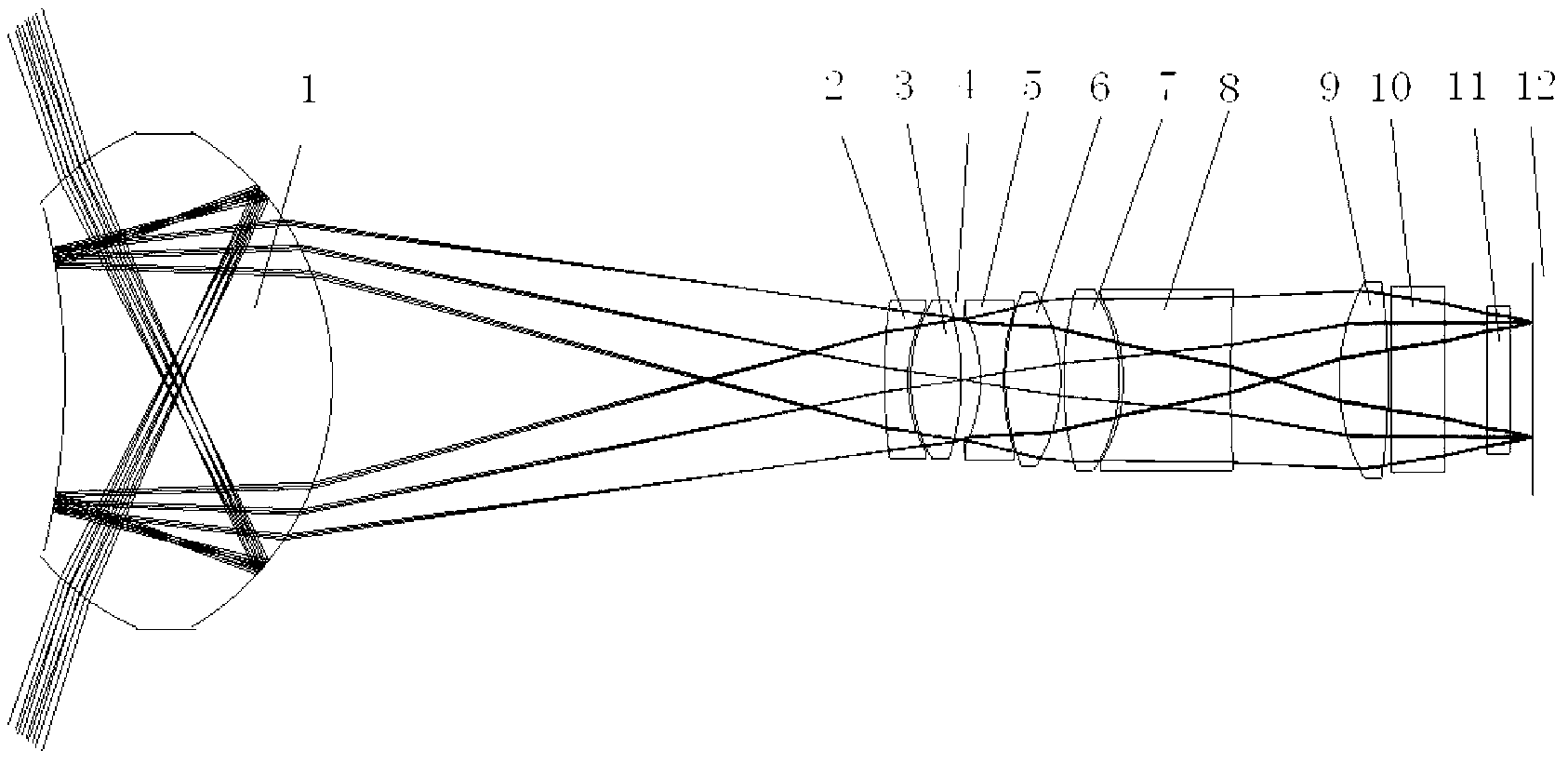
[0027] See attached figure 1 , the optical system of the ultraviolet multi-band panoramic imager, the optical system includes a catadioptric lens 1, a first fused silica concave lens 2, a first calcium fluoride convex lens 3, an aperture stop 4, a second fused quartz concave lens 5, the first Two calcium fluoride convex lenses 6, the third calcium fluoride convex lens 7, the third fused quartz concave lens 8, the fourth calcium fluoride convex lens 9, optical filter 10, detector protective cover 11, detector receiving image surface 12. The light beam emitted by the annular target passes through the catadioptric lens 1 and forms a virtual image, the virtual image is located on the left side of the exit surface of the catadioptric lens 1, the first fused quartz concave lens 2, the first calcium fluoride convex lens 3, the aperture stop 4, the first Two fused quartz concave lenses 5, the second calcium fluoride convex lens 6, the third calcium fluoride convex lens 7, the third f...

Embodiment 2

[0031] This embodiment is that the optical system of the ultraviolet multi-band panoramic imager of embodiment 1 is applied to space remote sensing atmospheric annular limb spectral imaging detection. The focal length of the optical system of the ultraviolet multi-band panoramic imager of this embodiment is 4.7mm, and the field of view is 70.2°×72.4 °, the working band is 250nm-380nm. Atmospheric annular limb scene is incident on the image plane 12 through catadioptric lens 1, relay lens group lens 2-9, optical filter 10, detector protective cover 11, and the band center wavelength of the first channel of optical filter 10 is 265nm , the central range of the second channel is 295nm, the central range of the third channel is 360nm, and the conversion of each channel is realized by replacing the filter 10. The total length of the optical system is 175mm, the diameter of catadioptric lens 1 is 52mm, the radius of curvature of the first surface is 30mm, the radius of curvature of ...


PUM


Abstract

The invention relates to an optical system of an ultraviolet multi-band panoramic imaging instrument, relating to the technical field of space optics and solving the problem that an optical system of a conventional ultraviolet limb annular imaging instrument cannot realize imaging of a 360-degree annular field of view. The optical system is composed of a reflecting and refracting lens, a relay lens group, an optical filter and an area array detector, wherein the optical system is made of an ultraviolet material with the waveband scope of 250 nm to 380 nm; and the multi-waveband imaging is realized by selecting optical filter with different central wavelengths. The aperture diaphragm of the system is located in the relay lens group; the entrance beam of the 360-degree annular field of view becomes a virtual image through the reflecting and refracting lens; the image surface of the virtual image is located in the reflecting lens; the relay lens group images the virtual image of the reflecting and refracting lens for the second time, and finally forms an image on the area matrix detector. As a reflecting surface and a refracting surface are combined together, the optical system is relatively small and compact in structure, is suitable to be used as an optical system for ultraviolet limb panoramic imaging on a satellite, and is applied to the fields, such as atmospheric remote sensing for aerospace and aviation, earth observation and the like.

Description

technical field [0001] The invention relates to the technical field of space optics, in particular to a miniaturized ultraviolet multi-band panoramic imager optical system. Background technique [0002] Panoramic imager is a space optical remote sensing instrument capable of realizing 360° annular imaging of the Earth's limb, and is widely used in space ultraviolet optical remote sensing, ozone observation, trace gas monitoring and other fields. In order to obtain more limbal atmospheric remote sensing information, the requirements for panoramic imagers are getting higher and higher. For example, the field of view of the instrument observation is getting bigger and bigger, and the band adaptability is getting stronger and stronger. [0003] For example, in the field of space atmospheric remote sensing that includes multiple ultraviolet bands, in the range of 250nm-380nm and limb height 10km-80km, in order to obtain more remote sensing information, it is necessary to detect ...

Claims


Application Information

Patent Timeline
Patent Type & Authority Applications(China)
IPC IPC(8): G02B13/06G02B13/14G02B17/08
Inventor 李博王淑荣于向阳王俊博
Owner CHANGCHUN INST OF OPTICS FINE MECHANICS & PHYSICS CHINESE ACAD OF SCI
Why Eureka
Try Eureka