Intelligent vacuum contactor

A vacuum contactor, intelligent technology, applied in high-voltage air circuit breakers, electrical components, electrical switches, etc., can solve the problems of complex process, temperature rise, increased safety risks, etc., to achieve compact volume space, easy installation, lightening product The effect of weight

Inactive Publication Date: 2015-05-06
ANHUI YUTENG VACUUM ELECTRICAL
View PDF3 Cites 0 Cited by
  • Summary
  • Abstract
  • Description
  • Claims
  • Application Information

AI Technical Summary

Problems solved by technology

[0002] At present, the vacuum contactor assembly used in the high, medium and low voltage switches of the coal mine explosion-proof power supply system has a structure: a vacuum contactor and a reversing switch are installed with a protector, and the connection is fixed with screws through a copper braid. The process is complicated, and because of too many connecting wires, it increases the safety risk of the product during operation
In addition, explosion-proof switches made of traditional vacuum contactors have technical and technical problems such as large volume, high temperature, manual reversing, and disordered internal wiring of the switch. More importantly, the existing explosion-proof switches have no obvious isolation fractures. , it is impossible for the user to directly observe its use status, which is prone to accidents

Method used


Image

  • Intelligent vacuum contactor
  • Intelligent vacuum contactor
  • Intelligent vacuum contactor

Examples


Embodiment 1

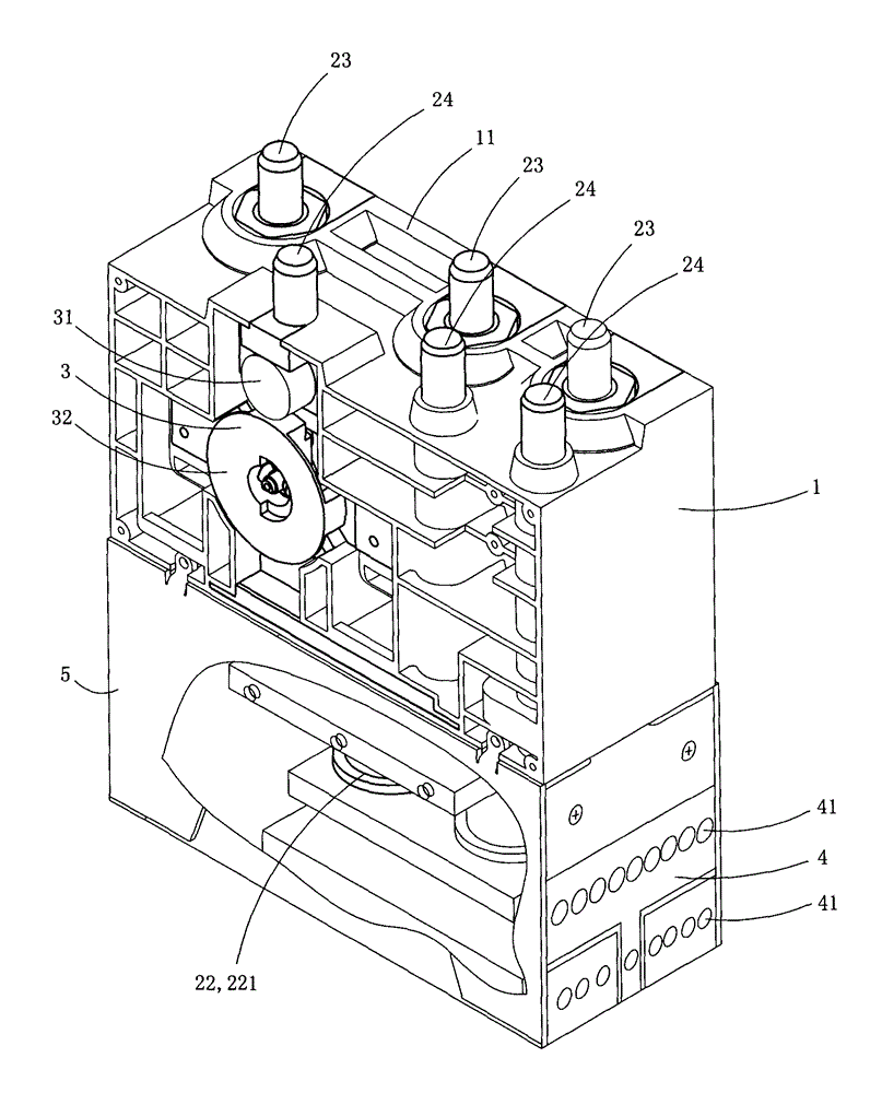
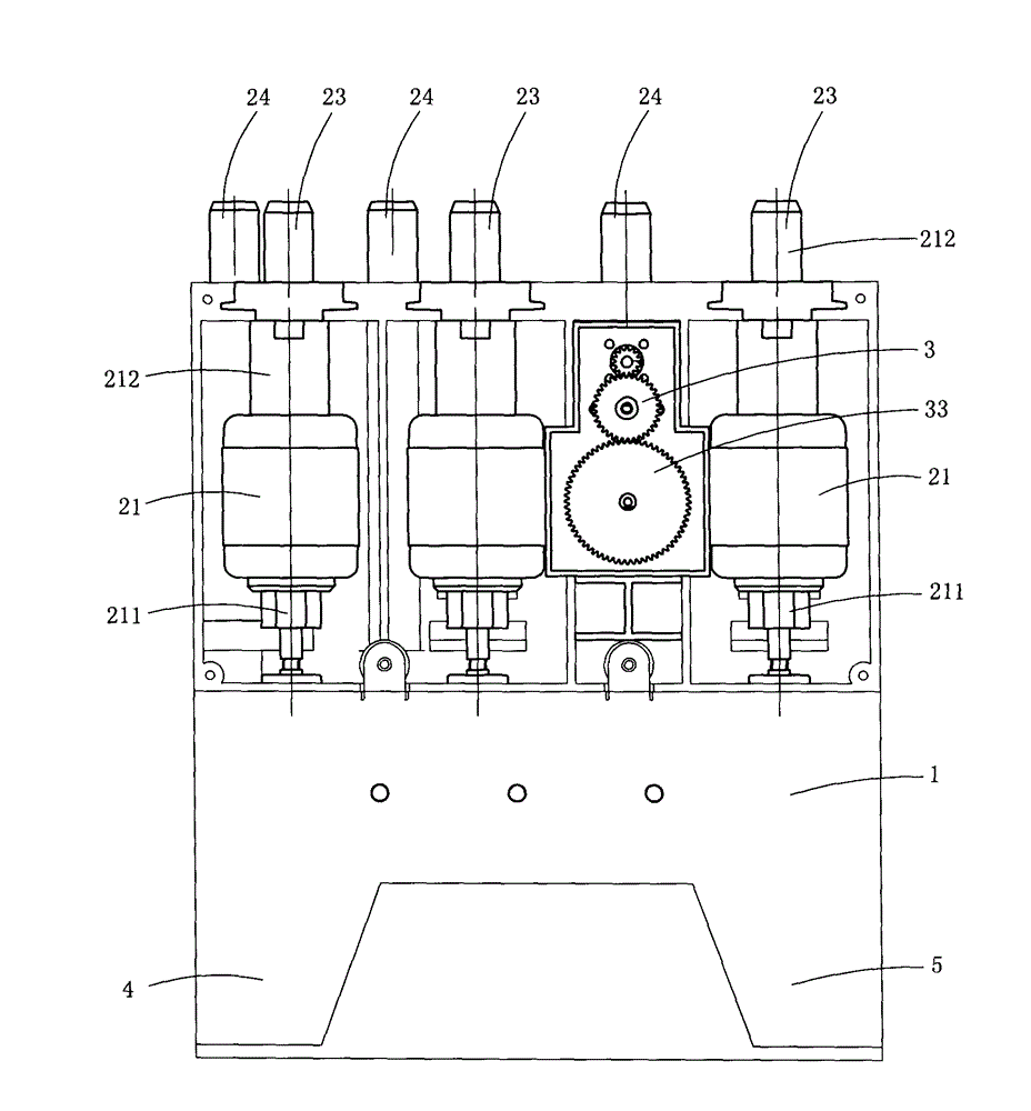
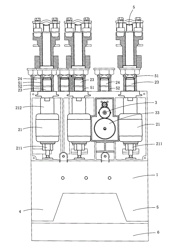
[0013] figure 1 and figure 2 A specific embodiment of the invention is shown in which figure 1 It is a schematic diagram of a three-dimensional structure of the present invention; figure 2 yes figure 1 A schematic diagram of the structure of the vacuum contactor shown when viewed from the other side.

[0014] This embodiment discloses an intelligent vacuum contactor, see figure 1 and figure 2 As shown, it includes a frame 1, a vacuum contactor 2, an electric reversing mechanism 3 and a comprehensive protector 4 arranged on the frame; the vacuum contactor, the electric reversing mechanism and the comprehensive protector are integrated through the frame.

[0015] The frame is preferably made of bakelite or reinforced nylon.

[0016] The vacuum contactor includes three vacuum switch tubes 21 arranged along the plumb line and a permanent magnet operating mechanism 22 arranged below the vacuum switch tubes. The permanent magnet operating mechanism drives the moving parts i...


PUM


Abstract

The invention discloses an intelligent vacuum contactor. The intelligent vacuum contactor comprises a frame, and a vacuum contactor, an electric steering mechanism and a comprehensive protector, which are arranged on the frame, wherein the vacuum contactor comprises three vacuum switch tubes and a permanent magnet type operation mechanism, the permanent magnet type operation mechanism drives moving contacts in the three vacuum switch tubes to perform switching motions, each static contact in each vacuum switch tube is stretched out of the wall of the frame, and a portion of each static contact, stretched out of the wall of the frame, is directly used as a plug-in type power side power connection pillar. The intelligent vacuum contactor directly integrates each static contacts in each vacuum switch tube with each power side power connection pillar, can reduce the self weight, is convenient to install, and simultaneously can greatly compress volume space, and conforms to development demands of miniaturization and intelligence of underground mining equipment.

Description

technical field [0001] The invention belongs to the technical field of vacuum contactor structure design, and in particular relates to an intelligent vacuum contactor. Background technique [0002] At present, the vacuum contactor assembly used in the high, medium and low voltage switches of the coal mine explosion-proof power supply system has a structure: a vacuum contactor and a reversing switch are installed with a protector, and are fixed and connected by screws through a copper braid. The process is complicated, and because there are too many connecting wires, the safety risk during product operation is increased. In addition, explosion-proof switches made of traditional vacuum contactors have technical and technical problems such as large volume, high temperature, manual reversing, and disordered internal wiring of the switch. More importantly, the existing explosion-proof switches have no obvious isolation fractures. , It is impossible for the user to directly watch...

Claims


Application Information

Patent Timeline
Patent Type & Authority Applications(China)
IPC IPC(8): H01H33/66
CPCH01H33/6606H01H33/666
Inventor 王明
Owner ANHUI YUTENG VACUUM ELECTRICAL
Why Eureka
Try Eureka