
Method for reducing electric leakage of trench gate structure semi-floating gate device

A technology of semi-floating gate devices and trench gates, applied in semiconductor devices, semiconductor/solid-state device manufacturing, circuits, etc., can solve problems such as current flow, leakage, and residual silicon on the sidewall of the oxide layer in the field, so as to reduce leakage and cost controllable effect

Inactive Publication Date: 2015-05-06
SHANGHAI INTEGRATED CIRCUIT RES & DEV CENT +1
View PDF4 Cites 3 Cited by
  • Summary
  • Abstract
  • Description
  • Claims
  • Application Information

AI Technical Summary

Problems solved by technology

[0007] However, although the semi-floating gate device in the above-mentioned invention patent application can increase the channel length through the U-shaped channel, reduce the unit area, and increase the chip density, due to the structure in the process of forming the U-shaped channel, it will cause on-site oxidation. The remaining silicon on the sidewalls of the layer causes some current in the device to flow in the direction of the remaining silicon between the sidewalls, resulting in leakage between the source and drain regions of the device without the application of a gate electrode Phenomenon

Method used


Image

  • Method for reducing electric leakage of trench gate structure semi-floating gate device
  • Method for reducing electric leakage of trench gate structure semi-floating gate device
  • Method for reducing electric leakage of trench gate structure semi-floating gate device

Examples


Embodiment Construction

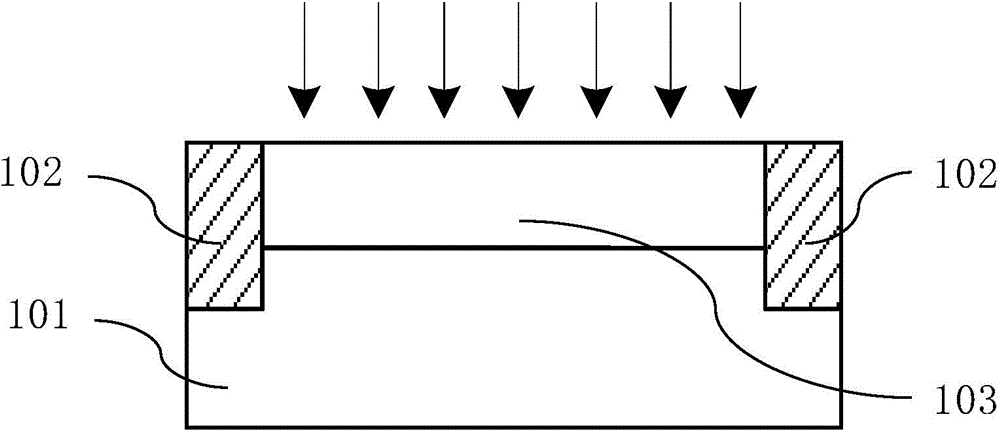
[0033] The specific embodiment of the present invention will be further described in detail below in conjunction with the accompanying drawings.

[0034] It should be noted that, in the following specific embodiments, when describing the embodiments of the present invention in detail, in order to clearly show the structure of the present invention for the convenience of description, the structures in the drawings are not drawn according to the general scale, and are drawn Due to partial enlargement, deformation and simplification, the size of the structure shown does not represent the actual size. At the same time, the drawings are schematic diagrams of idealized embodiments of the present invention, and the illustrated embodiments of the present invention should not be considered limited to the specific shapes of the regions shown in the drawings, but include shapes obtained, such as those caused by manufacturing. deviation etc. For example, the curves obtained by etching ar...


PUM

PropertyMeasurementUnit
Thicknessaaaaaaaaaa

Abstract

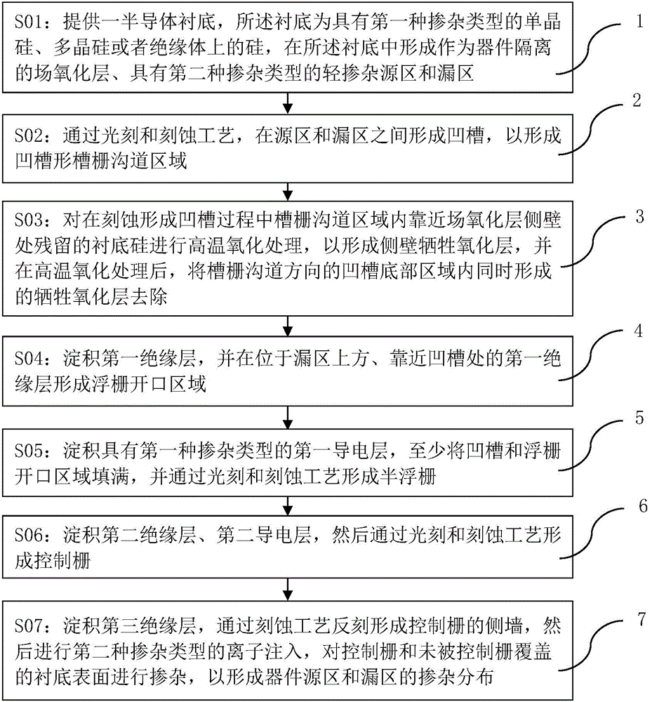
The invention discloses a method for reducing electric leakage of a trench gate structure semi-floating gate device. The method includes the step of performing oxidation treatment on silicon remaining at the position close to a field oxide layer side wall in a trench gate channel region during trench etching to form a side wall sacrificial oxide layer with an insulating effect, thereby preventing the current from flowing in the direction of the silicon remaining in the side wall, enabling the current to flow in the direction of a trench-shaped channel of the device and reducing the phenomenon of electric leakage between a source region and a drain region. The method for reducing electric leakage of the trench gate structure semi-floating gate device can be integrated with existing processes and is controllable in cost.

Description

technical field [0001] The present invention relates to the technical field of semiconductor memory, and more particularly, relates to a method for reducing electric leakage of semi-floating gate devices with trench gate (Trench Gate) structure by means of oxidation. Background technique [0002] As one of the basic core chips of electronic products, memory is widely used in various electronic products including mobile phones and mobile handheld products. Among them, the semi-floating gate device, as a new type of storage device, can be applied to different integrated circuits. [0003] Semi-floating gate memory can replace a portion of static random access memory (SRAM). Traditional SRAM requires 6 MOSFET transistors to form a storage unit, which has low integration and occupies a large area. The semi-floating gate transistor can form a storage unit with a single transistor, and its storage speed is close to that of a traditional SRAM storage unit composed of 6 transistor...

Claims


Application Information

Patent Timeline
IPC IPC(8): H01L21/335H01L21/8247
CPCH01L29/42336H01L29/42364
Inventor 庄翔孙德明王全
Owner SHANGHAI INTEGRATED CIRCUIT RES & DEV CENT
Learn More