Electrochemical energy storage device and method for controlling a cell module in an electrochemical energy storage device

A technology of battery modules and accumulators, applied in electrochemical generators, batteries, secondary batteries, etc., can solve the problems of considerable addressing costs and communication costs

Active Publication Date: 2015-05-06
ROBERT BOSCH GMBH
View PDF8 Cites 0 Cited by
  • Summary
  • Abstract
  • Description
  • Claims
  • Application Information

AI Technical Summary

Problems solved by technology

The described implementation is therefore also used today for battery modules, but when transferring the principle to the individual batteries, it has the disadvantage that the addressing and communication costs are considerable

Method used


Image

  • Electrochemical energy storage device and method for controlling a cell module in an electrochemical energy storage device
  • Electrochemical energy storage device and method for controlling a cell module in an electrochemical energy storage device
  • Electrochemical energy storage device and method for controlling a cell module in an electrochemical energy storage device

Examples


Embodiment Construction

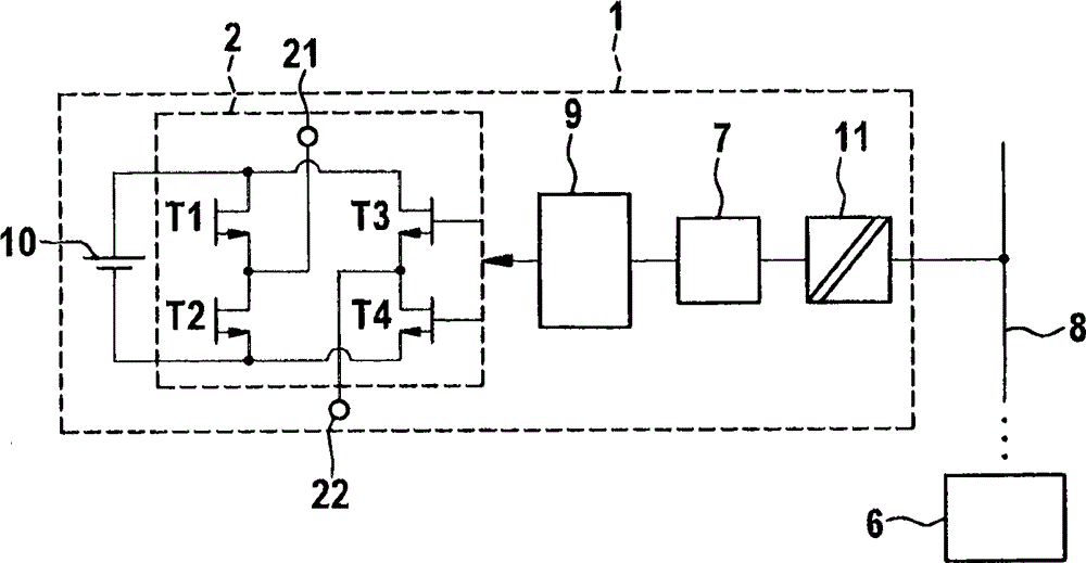
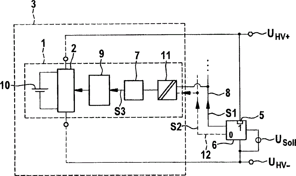
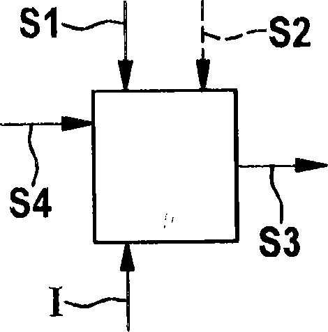
[0021] figure 2 shows the combination figure 1 A modification according to the invention of the device described at the outset. Through the voltage sensor 5 as a voltage determination device and the reference voltage U soll , the battery management system (BMS) 6 as the first processing means determines the regulation requirements for the first battery module 1 for establishing the desired terminal voltage U HV+ , U HV- . The BMS 6 sends the first signal S1 through the bus 8 . By means of this signal S1 , the battery module 1 is informed of a probability value, from which the microcontroller 7 as a second processing device generates a switching signal S3 and supplies it to the full bridge 2 via the driver 9 . A second bus 12 situated between the BMS 6 and the potential separation device 11 delivers a polarity indicator S2 to the microcontroller 7 as a second signal, by means of which the polarity of the first battery module 1 is reported to other A battery module (not s...


PUM


Abstract

The invention provides an electrochemical energy storage device and a method for controlling a cell module in the electrochemical energy storage device. according to the invention, a terminal voltage (UHV+, UHV-) of the electrochemical energy storage device (3) is determined, the terminal voltage (UHV+, UHV-) is compared with a rated value (Vsoll), a first signal (S1) is sent to the cell module (1) to establish a probability for achieving the nominal value (Vsoll)for a particular switching state, and a second signal (S2) is sent to the cell module (1), wherein the second signal (S2) represents the particular switching state of the cell module (1) with respect to the polarity of the electrochemical energy storage device (3).

Description

technical field [0001] The invention relates to the handling of battery modules in electrochemical cells or electrochemical energy stores. In particular, the invention relates to improvements in handling battery modules to reduce switching losses and signal transmission costs. Background technique [0002] In order to achieve different voltages with the aid of electrochemical energy stores, the cells of the electrochemical energy stores (generally “battery modules”) are wired in branch circuits which form a series circuit of battery modules. In addition, by connecting these branch circuits in parallel, the possible output current or current consumption can be increased. A known device for connecting multiple battery modules is in figure 1 shown in . figure 1 shows a topology of an electronic device for switching on, bridging or by means of a full bridge 2 comprising transistors T1, T2, T3, T4 and terminals for connection to an adjacent battery (not shown) 21 and 22) are ...

Claims


Application Information

Patent Timeline
Patent Type & Authority Applications(China)
IPC IPC(8): H01M10/42H01M10/48
CPCH01M10/425H01M10/48H01M10/42H01M2010/4278H01M2220/20Y02E60/10
Inventor S·布茨曼
Owner ROBERT BOSCH GMBH
Why Eureka
Try Eureka