Radial line feed medium resonant antenna array

A technology of dielectric resonant antenna and dielectric resonator, which is applied in the direction of antenna array, antenna, slot antenna, etc., can solve the problems of antenna efficiency reduction, feed loss, feed loss dielectric loss, etc., and achieve high gain, high aperture efficiency, Solve complex effects

Active Publication Date: 2015-05-06
BEIJING UNIV OF POSTS & TELECOMM
View PDF6 Cites 29 Cited by
  • Summary
  • Abstract
  • Description
  • Claims
  • Application Information

AI Technical Summary

Problems solved by technology

When the number of array elements is large and the gain is high, the microstrip patch coupling feeding method is used, which will cause the loss of the feeding due to the increase of the microstrip line
[0003] At present, the commonly used high-gain antennas for microwave communication are horn antennas, microstrip antenna arrays, reflectarray antennas, and radial line antennas. Among them, the horn antennas and reflectarray antennas are large in size and are easily affected by the environment. Feed loss and dielectric loss are relatively serious during application, resulting in reduced antenna efficiency
Radial line antennas have been widely studied as high-gain antennas. The main direction of research is to optimize the distribution and length of slots on the aperture to enhance the efficiency of the antenna, and use other types of antennas to load radial line antennas to optimize radiation gain and aperture efficiency. and radiation efficiency have been less studied

Method used


Image

  • Radial line feed medium resonant antenna array
  • Radial line feed medium resonant antenna array
  • Radial line feed medium resonant antenna array

Examples


Embodiment 1

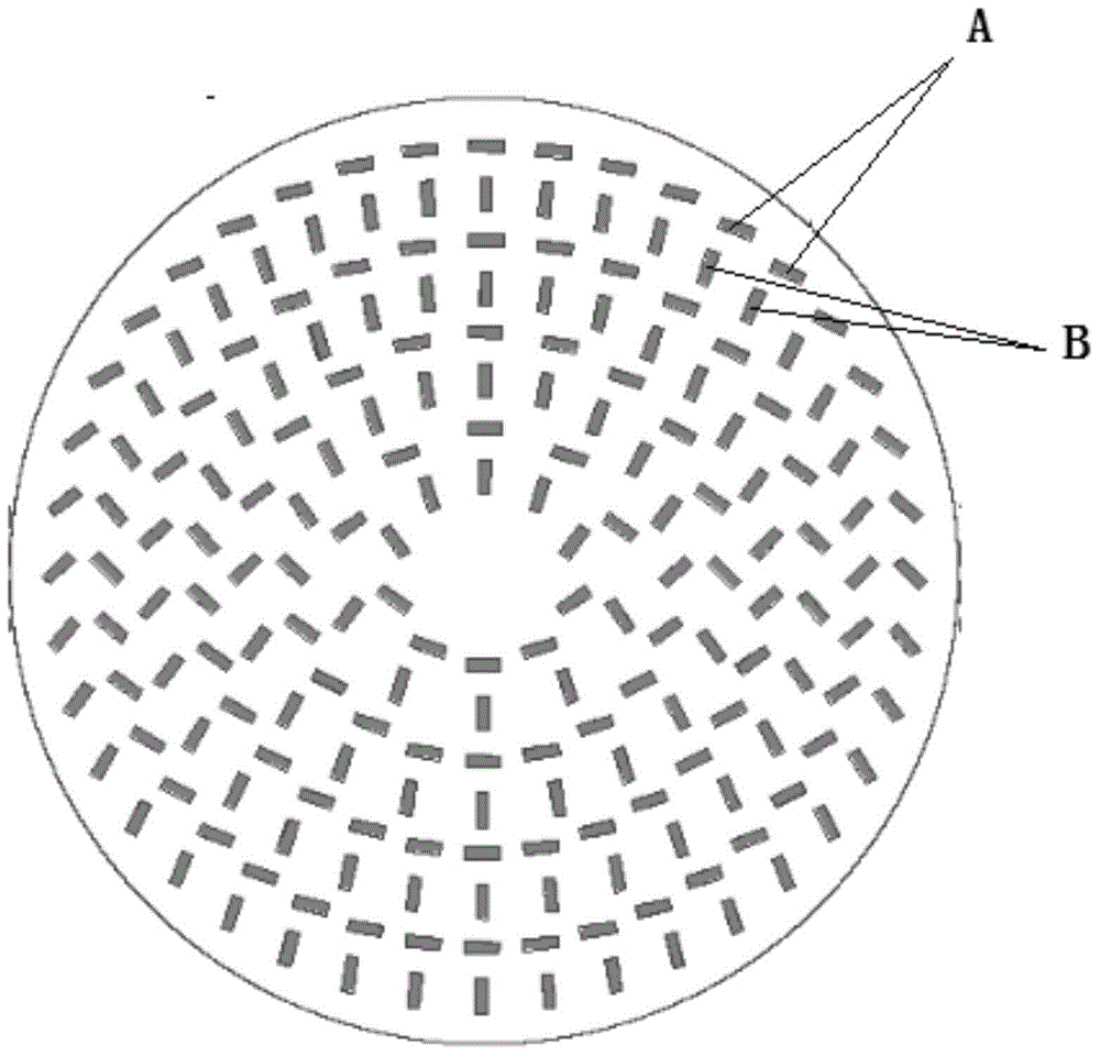
[0033] figure 2 An arrangement scheme of radial line-fed dielectric resonant antenna array radiating linearly polarized electromagnetic waves is shown. Since the arrangement of the dielectric resonator antenna array is the same as the arrangement of the slots of the upper unsealed metal plate, only the arrangement of the dielectric resonator antenna array is described here.

[0034] As can be seen, figure 2 The array units of the medium dielectric resonant antenna array are arranged in multiple circles (4 circles in the figure), and each circle includes several array units. In the radial direction, there is a waveguide wavelength between each circle of array units, and a circle of arrays near the edge The element is one-quarter waveguide wavelength from the sidewall of the surface-slotted radial line waveguide. In each circle, each array unit is composed of two mutually perpendicular three-dimensional rectangular dielectric resonators, which are respectively set as A diele...

Embodiment 2

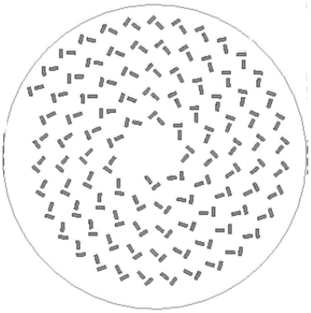
[0062] image 3 An arrangement scheme in which the radial line-fed dielectric resonant antenna array radiates circularly polarized electromagnetic waves is shown. Similarly, the arrangement of the dielectric resonator antenna array is the same as the arrangement of the slots of the upper unsealed metal plate, and only the arrangement of the dielectric resonator antenna array is described here.

[0063] and figure 2 The characteristics are similar. In this arrangement, the dielectric resonant antenna array is also composed of a series of array units, and each array unit includes two mutually perpendicular three-dimensional rectangular dielectric resonators. The difference is that the two mutually perpendicular dielectric resonators are relatively close to each other. If the center of each dielectric resonator is connected to the center of the circle, the angle between the long sides of the two mutually perpendicular dielectric resonators and their respective center lines sam...


PUM


Abstract

The invention discloses a radial line feed medium resonant antenna array. The radial line feed medium resonant antenna array comprises a surface-slotted radial line waveguide (1), a feed probe (2) and a medium resonant antenna array (3). The surface-slotted radial line waveguide (1) comprises an upper slotted metal plate (1a) and a lower metal bottom plate (1b); the feed probe is composed of a metal bar (2a) and a radio antenna terminal (2b) connected with the metal bar (2a) and is arranged on the axis of the surface-slotted radial line waveguide (1); one end of the radio antenna terminal (2b) extends out of the surface-slotted radial line waveguide (1); the medium resonant antenna array (3) is arranged right above the upper slotted metal plate (1a) and comprises a plurality of unit medium resonators. The radial line feed medium resonant antenna array achieves linear-polarized or circular-polarized electromagnetic radiation through a single-feed mode and meanwhile is simple in structure and high in gain and aperture efficiency.

Description

technical field [0001] The invention relates to the field of microwave communication, and more specifically relates to a single-feed radial line waveguide excitation dielectric resonant antenna array. Background technique [0002] Dielectric resonant antennas have the advantages of high radiation efficiency, low loss, small size and large design freedom, so they have been widely studied and applied to practical work. At present, the feeding methods of the antenna array composed of dielectric resonators include probe coupling energy feeding in the rectangular waveguide, slot feeding on the substrate integrated waveguide, coupling energy from the dielectric waveguide, and microstrip patch coupling feeding, etc. . Among them, the probe coupling feeding method requires a probe for each array unit, and it is necessary to adjust the distance of each probe deep into the waveguide to adjust the coupling degree; the substrate integrated waveguide slot feeding and feeding from the di...

Claims


Application Information

Patent Timeline
Patent Type & Authority Applications(China)
IPC IPC(8): H01Q1/36H01Q13/10H01Q21/24H01Q21/00
Inventor 刘元安苏明原琳黎淑兰于翠屏吴永乐王卫民
Owner BEIJING UNIV OF POSTS & TELECOMM
Why Eureka
Try Eureka