
Active power filter based on inverter side current feedback and current control method of active power filter

A power filter, inverter technology, applied in active power filtering, AC network to reduce harmonics/ripple, AC power input conversion to DC power output, etc., can solve the problem of reducing stability and control accuracy, increasing Damping loss, multiple sensors, etc., to achieve the effect of large stability margin and damping effect, good resonance suppression ability, and improved control accuracy

Inactive Publication Date: 2015-05-06
STATE GRID CORP OF CHINA +3
View PDF3 Cites 9 Cited by
  • Summary
  • Abstract
  • Description
  • Claims
  • Application Information

AI Technical Summary

Problems solved by technology

The passive damping method does not need to use complex control algorithms, and the control system is simple and stable. The main problem is the addition of additional damping losses
The active damping method enhances the system damping through the control algorithm. For example, the existing state feedback and deadbeat control method has better performance, but requires more sensors; The resonance peak value is reduced below 0dB without additional sensors, but the additional delay in the closed-loop control system will also reduce the overall stability and control accuracy of the system; relatively speaking, the grid-side current feedback control method using capacitive current feedback is relatively Typical Effective Control Methods
[0004] The closed-loop control system using inverter-side current feedback is easier to stabilize. The main problem is that due to the existence of the LCL filter, there is an error between the inverter-side controlled current and the grid-side output current, which affects the APF harmonics. Inhibition effect; at the same time, there is a possibility of resonance between the filter capacitor and the grid-side inductance and grid parameters

Method used


Image

  • Active power filter based on inverter side current feedback and current control method of active power filter
  • Active power filter based on inverter side current feedback and current control method of active power filter
  • Active power filter based on inverter side current feedback and current control method of active power filter

Examples


Embodiment Construction

[0019] The present invention will be further described in detail through the following examples in conjunction with the accompanying drawings. The following examples are explanations of the present invention and the present invention is not limited to the following examples.

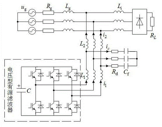
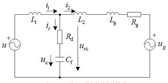
[0020] Such as figure 1 As shown, an active power filter based on inverter side current feedback of the present invention includes an APF system and an LCL filter, and the APF system is a three-phase bridge parallel structure. The APF system includes three-phase grid power u g , load rectifier and voltage-type active filter, the LCL filter contains three sets of inverter side inductance L 1 , Grid side inductance L 2 , filter capacitor C f and damping resistor R d , three-phase grid power u g The three-phase input terminals are connected to each other, and the three-phase grid power supply u g The three-phase output terminals are respectively connected to the three input terminals of the load recti...


PUM


Abstract

The invention discloses an active power filter based on inverter side current feedback and a current control method of the active power filter. The active power filter comprises an APF (active power filter) system and an LCL filter, and the APF system is in a three-phase bridge type parallel structure. The current control method includes that feedback current of a current closed-loop control system takes inverter side current i1, a master controller GA (s) adopts PI control, and capacitance current feedback control is adopted. By means of feedback adjustment of LCL filter capacitance current on the basis of traditional feedback control of single inverter side current, control precision of the system is improved while resonance of the LCL filter and power grid parameters can be restrained.

Description

technical field [0001] The invention relates to an active power filter based on inverter side current feedback and a current control method thereof, belonging to the field of active power filter control. Background technique [0002] High-frequency switching harmonics are an inevitable product of PWM rectifiers. For Active Power Filters (APF) that compensate for grid harmonics, it should be avoided that their high-frequency harmonics flow into the grid and cause secondary pollution to the grid. For this reason, people usually install an output filter on the grid-connected side of the device. Compared with other filters such as the L single-inductor type, the LCL type filter has a better filtering effect and requires a smaller filter inductance, but the LCL filter is prone to resonance, which affects the stability of the system. [0003] The current closed-loop control feedback current of the LCL type APF can select the inverter side current and the grid side current. The c...

Claims


Application Information

Patent Timeline
IPC IPC(8): H02J3/01
CPCH02J3/01H02M7/5387Y02E40/20
Inventor 许杏桃许胜王益明陈群黄文静李然许杏明沈鹏
Owner STATE GRID CORP OF CHINA
Learn More