Disk type torque limiting permanent magnet coupler
A permanent magnetic coupler and torque-limiting technology, which is applied in the direction of electrical components, electromechanical devices, electromechanical transmission devices, etc., can solve the problems that the magnet end can only be installed on the load side, manufacturing and processing, installation and debugging difficulties, and influence on operation stability, etc. , to achieve the effects of light weight, convenient manufacturing and processing, and precise control of air gap size
- Summary
- Abstract
- Description
- Claims
- Application Information
AI Technical Summary
Problems solved by technology
Method used
Image

Examples
Embodiment 1
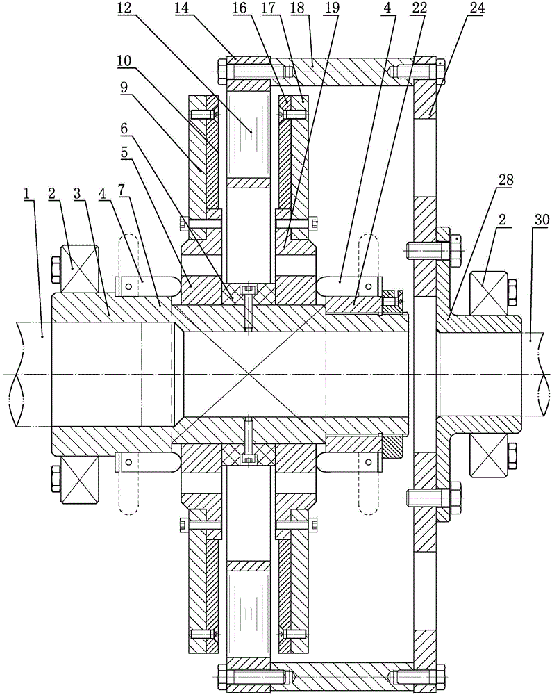
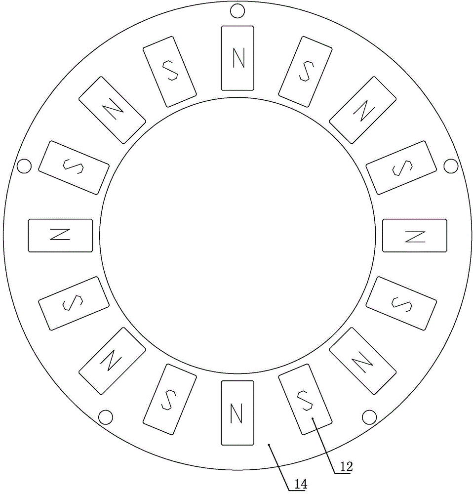
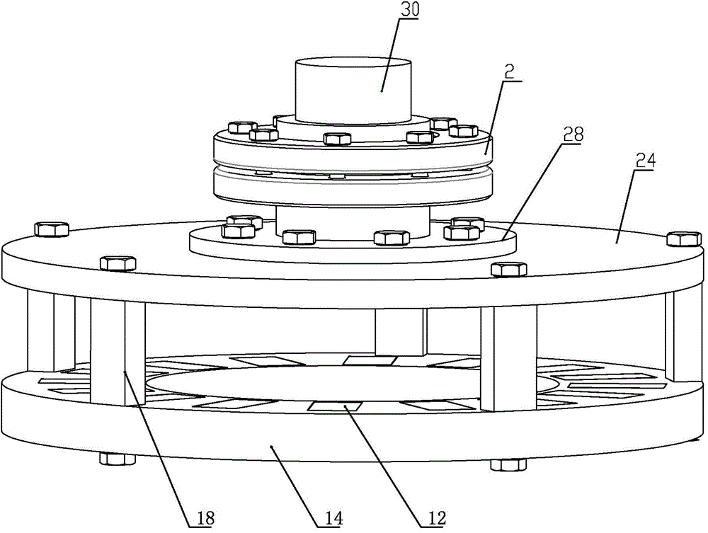
[0024] see figure 1 and figure 2 as well as Figure 4 , the disc-type torque-limiting permanent magnet coupler of the present invention includes a split and coaxial first shaft 1 and a second shaft 30, the first shaft 1 is sleeved in the first shaft sleeve 3, and the first shaft sleeve 3 is outer The sliding sleeve I5 is connected, and a part of the first shaft sleeve 2 is a square shaft 8, which is matched with the square hole on the sliding sleeve I5. The sliding sleeve I5 is connected to the conductor turntable I through bolts. The conductor turntable I includes a steel plate I9 and a conductive conductor plate I10. The sliding sleeve I5 is connected to the steel plate I9 by bolts, and the steel plate I9 and the conductor plate I10 are connected by bolts; the sliding sleeve I5 on the first shaft sleeve 3 is provided with limiting structures on both ends;
[0025] The second shaft 30 is socketed in the second shaft sleeve 28, the second shaft sleeve 28 is connected to the...
PUM
 Abstract
Description
Claims
Application Information
 - R&D
- Intellectual Property
- Life Sciences
- Materials
- Tech Scout
- Unparalleled Data Quality
- Higher Quality Content
- 60% Fewer Hallucinations
Browse by: Latest US Patents, China's latest patents, Technical Efficacy Thesaurus, Application Domain, Technology Topic, Popular Technical Reports.
© 2025 PatSnap. All rights reserved.Legal|Privacy policy|Modern Slavery Act Transparency Statement|Sitemap|About US| Contact US: help@patsnap.com