
A Harmonic Current Compensation System for High Speed ​​Permanent Magnet Motor Based on Space Vector Modulation

A space vector modulation and harmonic current technology, applied in vector control systems, control systems, control generators, etc., can solve problems such as control errors and ignoring harmonic components, achieve accurate calculation, accurate extraction, and reduce system reliability. Effect

Active Publication Date: 2017-10-20
BEIHANG UNIV
View PDF3 Cites 0 Cited by
  • Summary
  • Abstract
  • Description
  • Claims
  • Application Information

AI Technical Summary

Problems solved by technology

For example, optimize the design of the motor body and improve the sine degree of the air-gap magnetic field distribution, but such methods can only suppress the current harmonics caused by the distortion of the air-gap magnetic field; in view of the nonlinear characteristics of the PWM inverter, the current feedback type voltage compensation method is used. Voltage compensation, but this method can only compensate the 5th and 7th current harmonics caused by the nonlinear characteristics of the PWM inverter; the voltage compensation amount is calculated according to the mathematical model of the permanent magnet motor for voltage compensation, and this method can suppress the The 5th and 7th current harmonics caused by the nonlinear characteristics of the inverter and the distortion of the air gap magnetic field, but some harmonic components have been ignored when the mathematical model is established, and the harmonic current feedback loop has not been added. For the current harmonics of low-speed motors Wave suppression has achieved good results, but for high-speed motors, it will cause large control errors

Method used


Image

  • A Harmonic Current Compensation System for High Speed ​​Permanent Magnet Motor Based on Space Vector Modulation
  • A Harmonic Current Compensation System for High Speed ​​Permanent Magnet Motor Based on Space Vector Modulation
  • A Harmonic Current Compensation System for High Speed ​​Permanent Magnet Motor Based on Space Vector Modulation

Examples


Embodiment Construction

[0046] The present invention will be further described below in conjunction with the accompanying drawings and specific embodiments.

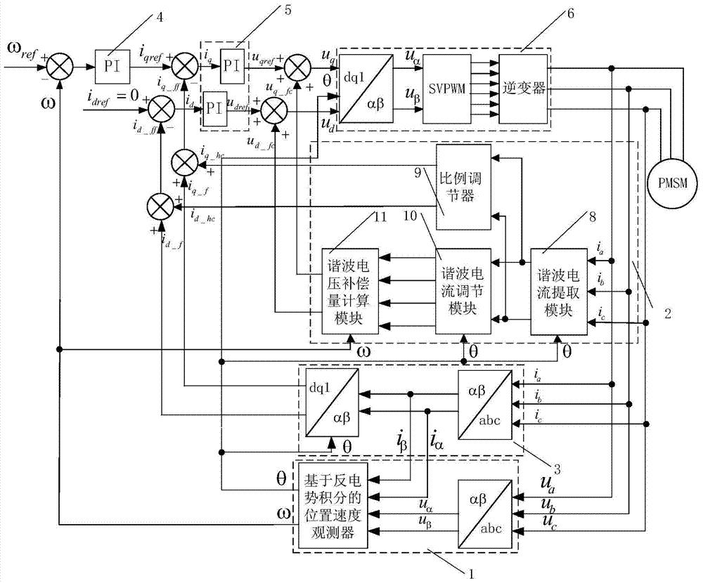
[0047] Such as figure 1 As shown, the present invention mainly consists of a rotor position and speed observation module (1), a stator phase current harmonic compensation module (2), a phase current feedback module (3), a rotational speed PI adjustment module (4), and a current PI adjustment module (5) , SVPWM conversion output module (6) is composed.

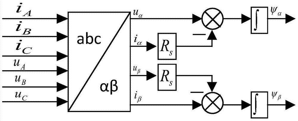
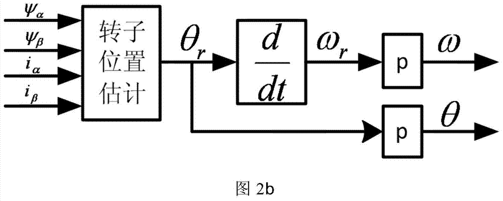
[0048] The position and speed observation module (1) is connected to the motor body, and is used to observe the rotor angular position θ of the permanent magnet synchronous motor r and angular velocity ω r , according to θ r and ω r And the number of pole pairs p calculates the rotor electrical angle θ=pθ of the permanent magnet synchronous motor r And the rotor electrical angular velocity ω=pω r ;

[0049] The stator phase current harmonic compensation module (2) is connected to the moto...


PUM


Abstract

The invention discloses a high-speed permanent magnet motor harmonic current compensation system based on space vector modulation. The system includes: a rotor position and speed observation module, a stator phase current harmonic compensation module, a phase current feedback module, and a rotational speed PI adjustment module. Current PI adjustment module, SVPWM conversion output module; Among them, the stator phase current harmonic compensation module includes: Harmonic current extraction module, which extracts the phase current harmonics of the permanent magnet synchronous motor in real time through an adaptive band-pass filter; The harmonic current adjustment is fed back to the current loop; the harmonic current adjustment module and the harmonic voltage compensation amount calculation module calculate the harmonic voltage compensation amount based on the high-speed permanent magnet motor mathematical model and feed it back to the voltage loop. The system can accurately calculate the voltage compensation amount and perform real-time compensation, effectively improve the phase current waveform in the operation of the permanent magnet synchronous motor, reduce the torque and speed ripple, and then improve the efficiency, stability and reliability of the motor operation.

Description

technical field [0001] The invention belongs to the technical field of permanent magnet synchronous motor control, and more specifically relates to a system for controlling current harmonics during the operation of a high-speed permanent magnet motor. Background technique [0002] A high-speed motor refers to a motor whose speed exceeds 10000r / min. Compared with traditional motors, high-speed permanent magnet synchronous motors have the characteristics of compact structure, small size, high efficiency, high power density, and fast response speed. They have broad applications in the fields of micro gas turbines, high-speed machine tools, blowers, compressors, and molecular pumps. The application prospect is becoming a research hotspot in the international electrotechnical field. During the operation of the permanent magnet synchronous motor, due to the characteristics of the dead time of the switching device of the PWM inverter, the tube voltage drop, and the distortion of t...

Claims


Application Information

Patent Timeline
Patent Type & Authority Patents(China)
IPC IPC(8): H02P21/22
Inventor 刘刚张强郑世强韩邦成毛琨陈宝栋
Owner BEIHANG UNIV
Learn More