Water inlet structure of upward flow filter tank

A water inlet and filter technology, which is applied in the field of water treatment, can solve problems such as the inability to fold down the drainage main canal, the difficulty in setting up water inlet and overflow measures, and the restriction of the elevation layout of the filter tank, so as to save land and construction costs and avoid valves. Installation and maintenance are difficult and the effect of improving flexibility

Pending Publication Date: 2021-02-26
SHANGHAI MUNICIPAL ENG DESIGN INST GRP +1
View PDF0 Cites 0 Cited by
  • Summary
  • Abstract
  • Description
  • Claims
  • Application Information

AI Technical Summary

Problems solved by technology

Since the water inlet electric valve is installed vertically and is exposed, it is often located near the floor, making installation and maintenance difficult, which limits the elevation layout of the filter tank
In addition, due to the space limitation of the valve, it is impossible to stack the main drainage canal under the water main canal, and it is difficult to set up overflow measures for the water intake

Method used


Image

  • Water inlet structure of upward flow filter tank
  • Water inlet structure of upward flow filter tank
  • Water inlet structure of upward flow filter tank

Examples


Embodiment 1

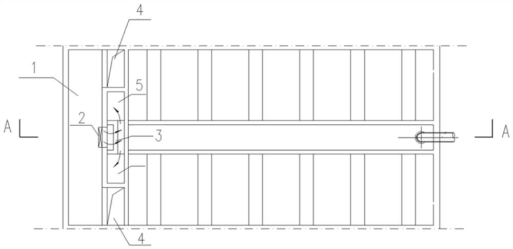
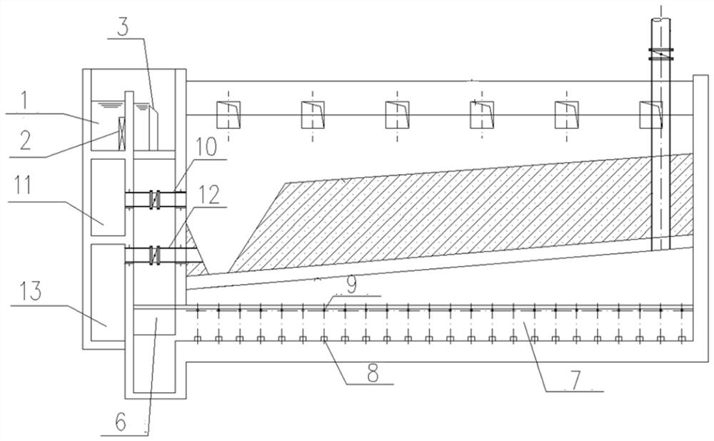
[0017] The upflow carbon filter with a central channel adopts this water intake method, including the main water intake channel 1, the single filter tank inlet valve 2, the water inlet weir 3 and the vertical shaft 5, and a double-layer central channel is set in the middle of the filter tank. The upper layer of the canal is equipped with water production and drainage channels, and the lower layer is equipped with water distribution and gas distribution channels. It is characterized in that the single-cell filter inlet valve 2 is arranged in front of the water inlet weir 3; On both sides of the gas channel, the inner side wall of the shaft 5 (that is, the side wall of the vertical shaft 5 on the side of the central water distribution channel facing the middle side, that is, the side wall facing the vertical shaft on the other side) continues to extend downward from the bottom plate of the vertical shaft to below The lower edge of the air distribution hole 9 of the water and gas ...

Embodiment 2

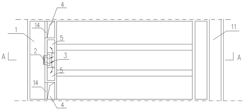
[0022] The upflow carbon filter without a central channel adopts the water inlet method, including the main water inlet channel 1, the single-cell filter water inlet valve 2, the water inlet weir 3 and the vertical shaft 5, and the characteristic is that the single-cell filter tank The valve 2 is arranged in front of the water inlet weir 3; the vertical shaft 5 is connected up and down, and the bottom plate of the well is deep, and a water seal baffle 6 is set at the connection between the vertical shaft 5 and the bottom water distribution channel 7. As shown in the figure, the inner side wall of the vertical shaft 5 extends downwards to 50-200mm lower than the lower edge of the air distribution hole 9 of the water distribution and air distribution channel to form a water seal baffle 6, and the remaining side walls are connected to the bottom plate of the vertical shaft. An overflow well 4 is arranged outside the vertical shaft 5, and an overflow weir 14 is arranged between the...


PUM


Abstract

The invention provides a water inlet structure of an upward flow filter tank, which comprises a water inlet main canal, a single-grid filter tank water inlet valve, a water inlet weir and a vertical shaft, and is characterized in that the single-grid filter tank water inlet valve is arranged in front of the water inlet weir; and the vertical shaft is vertically-through, the bottom plate of the vertical shaft is lower than the bottom of a water and gas distribution channel, and a water seal baffle is arranged at the joint of the vertical shaft and the bottom water and gas distribution channel.A water inlet mode different from that of a traditional upward flow filter tank is adopted, and the problems that a valve is difficult to install and maintain, the elevation arrangement of a tank bodyis limited, and overflow measures do not exist due to the fact that a valve is arranged on a traditional water inlet vertical pipe are solved. In addition, a sump at the bottom of the vertical shaftcan facilitate emptying of accumulated water during maintenance. A connecting channel of the vertical shaft and the water and gas distribution channel can facilitate entering of maintainers, and a manhole which needs to be additionally formed in a traditional water inlet mode is omitted.

Description

technical field [0001] The invention relates to the technical field of water treatment, and relates to a water inlet structure of an upward flow filter. Background technique [0002] The water intake method of the existing upward flow filter is that the water enters the water intake standpipe through the turning weir, and then enters the filter tank for filtration through the water distribution channel and the air distribution channel. An electric valve is set on the water inlet riser to control the water inlet, and closing the valve during air flushing can prevent the gas from escaping through the water inlet riser. Since the water inlet electric valve is installed vertically and is exposed, it is often located near the floor, making installation and maintenance difficult, which limits the elevation layout of the filter tank. In addition, due to the space limitation of the valve, it is impossible to stack the main drainage canal under the water main canal, and it is diffic...

Claims


Application Information

Patent Timeline
Patent Type & Authority Applications(China)
IPC IPC(8): B01D24/10B01D24/40B01D24/46
CPCB01D24/10B01D24/40B01D24/4631B01D24/4636
Inventor 邬亦俊刘志远周婷如芮旻马永恒张增荣吴国荣
Owner SHANGHAI MUNICIPAL ENG DESIGN INST GRP
Why Eureka
Try Eureka