Acoustic sensor with a diaphragm made of a composite fiber material

A fiber composite material and acoustic sensor technology, which is applied in the field of acoustic sensors to achieve the effects of low manufacturing cost, simple manufacturing and low material cost

Active Publication Date: 2015-05-06
ROBERT BOSCH GMBH
View PDF10 Cites 6 Cited by
  • Summary
  • Abstract
  • Description
  • Claims
  • Application Information

AI Technical Summary

Problems solved by technology

If the sensor is narrowband, echo signals with shif

Method used


Image

  • Acoustic sensor with a diaphragm made of a composite fiber material
  • Acoustic sensor with a diaphragm made of a composite fiber material
  • Acoustic sensor with a diaphragm made of a composite fiber material

Examples


Embodiment Construction

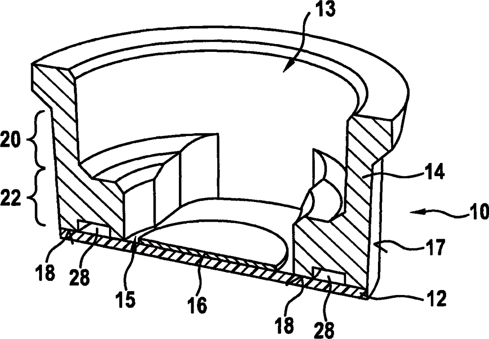
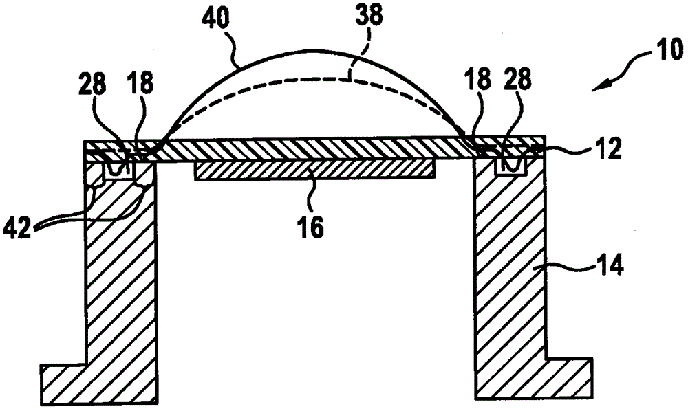
[0040] figure 1 The structure of an acoustic sensor 10 , which is designed as a pot transducer, is schematically shown. The acoustic sensor comprises a membrane 12 which is produced from a fiber composite material, for example carbon fiber reinforced plastic. Membrane 12 is connected to piezoelectric actuator 16 , which transmits the electromechanical interaction of acoustic sensor 10 as a transducer element. Furthermore, piezo actuators 16 are connected via openings 13 to electronic adjustment and control elements, which are in figure 1 not shown in

[0041] In order to form the pot converter 10 , the sensor housing 14 is formed as a hollow body which is open at both end faces 13 , 15 . Here, an end face 15 of the hollow body 14 is connected to the membrane 12 . For example, the membrane 12 can be glued to the bearing surface 18 of the sensor housing or of the hollow body 14 . Furthermore, the surrounding side wall 17 of the sensor housing 14 includes two wall sections 2...


PUM


Abstract

The invention relates to an acoustic sensor (10) comprising a diaphragm (12) which can oscillate and which has a converter element (16) and comprising a sensor housing (14), wherein the diaphragm (12) is fabricated from a composite fibre material and is connected as a separate component to the sensor housing (14). The invention also relates to a use of the acoustic sensor (10) and to a method for manufacturing same.

Description

technical field [0001] The invention relates to an acoustic sensor comprising a sensor housing and a vibration-capable diaphragm with a piezoelectric actuator. The invention also relates to the use of said sensor and its manufacturing method. Background technique [0002] In general, an acoustic sensor converts an acoustic signal or a variable sound pressure caused by the acoustic signal into an electrical signal, in particular a voltage. In this case an acoustic sensor is used as a receiver. Conversely, an acoustic sensor can also function as a transmitter, which converts an electrical signal into an acoustic signal. In order to receive acoustic signals from or transmit acoustic signals to a space, a combination of vibration-capable diaphragms combined with piezo-electric actuators is often used in order to bring about an electromechanical interaction. The mode of operation of such a sensor is based on a direct relationship between the elastic deformation of the membrane...

Claims


Application Information

Patent Timeline
IPC IPC(8): G10K9/122G10K13/00G01S15/93G01S7/521G10K9/20G01S15/931
CPCG01S7/521G01S15/931G10K9/122G10K9/20G10K13/00G01S2015/938
Inventor D·巴尔特伊拉F·凯泽
Owner ROBERT BOSCH GMBH
Why Eureka
Try Eureka