Shear wave crest value waveform correction method, device and system and application thereof

A correction method and shear wave technology, applied in the field of ultrasound images, can solve the problems of shear wave velocity calculation error, shear wave peak value determination error, low shear wave amplitude, etc. The effect of the signal-to-noise ratio

Active Publication Date: 2015-05-13
SONOSCAPE MEDICAL CORP
View PDF8 Cites 10 Cited by
  • Summary
  • Abstract
  • Description
  • Claims
  • Application Information

AI Technical Summary

Problems solved by technology

Moreover, when measuring viscous or soft tissues, the peak part of the shear wave presents a flat peak. If the noise is superimposed on the shear wave waveform, the position of the actually found maximum value of the waveform may deviate from the real peak position of the shear wave, resulting in an error in the calculation of the shear wave velocity
Moreover, for the shear wave elastography based on the acoustic radiation force, the amplitude of the shear wave is very low, and it is easy to appear an isolated maximum point far away from the shear wave peak, resulting in an error in the determination of the shear wave peak

Method used


Image

  • Shear wave crest value waveform correction method, device and system and application thereof
  • Shear wave crest value waveform correction method, device and system and application thereof
  • Shear wave crest value waveform correction method, device and system and application thereof

Examples


Embodiment 1

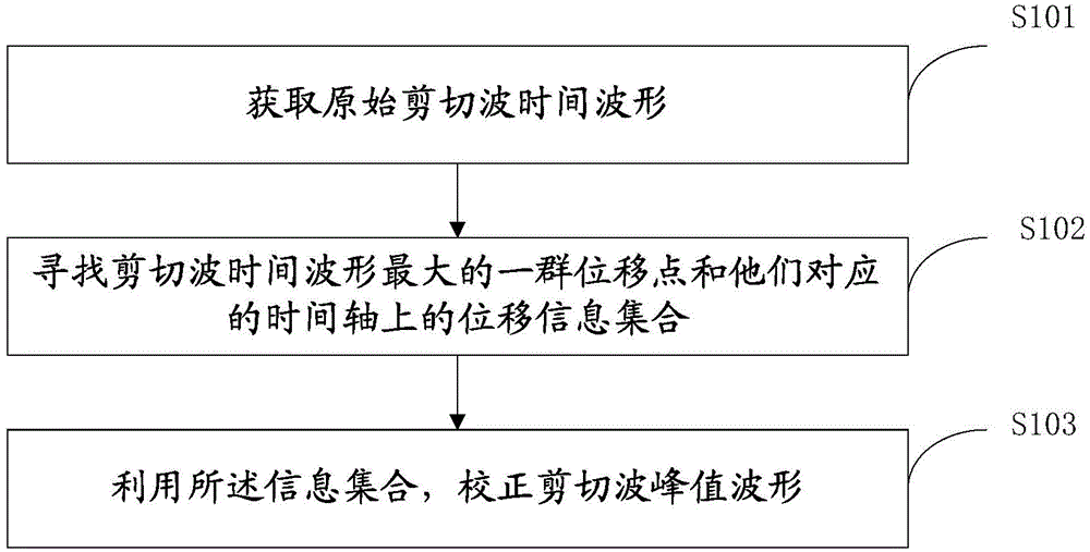
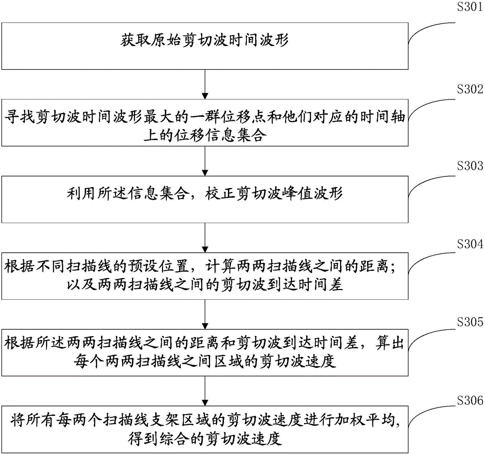
[0048] Such as figure 1 , 7 , 8, 9, and 10 are schematic flow charts of the method for correcting the shear wave peak waveform of the present invention. The present invention proposes a method for shear wave peak waveform correction, said method comprising the steps of:

[0049] S101. Acquire the original shear wave time waveform.

[0050] Such as Figure 9 A (indicated by the black solid line) shows the waveform of a shear wave actually detected, and F is the actual correct waveform of the shear wave (indicated by the red solid line). It can be seen that due to the influence of noise, the waveform does not rise and fall smoothly, but has many irregular fluctuations. If the maximum value of the waveform is directly used as the arrival time of the shear wave according to the conventional method, then the time position will fall at point E, that is. But looking at the entire shear wave waveform, the center of the theoretical waveform is obviously not point E.

[0051] S102...

Embodiment 2

[0079] As shown in the figure, it is an overall schematic diagram of a shear wave peak correction device of the present invention. The apparatus 200 includes: an acquisition unit 201 ; a first calculation unit 202 ; and a second calculation unit 203 .

[0080] The first acquisition unit 201 is configured to acquire the original shear wave time waveform;

[0081]The first calculation unit 202 is used to find a group of displacement points with the largest shear wave time waveform and their corresponding displacement information sets on the time axis;

[0082] The second calculation unit 203 is configured to use the information set to correct the shear wave peak waveform.

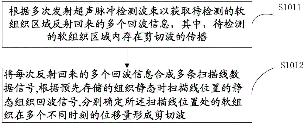
[0083] The first acquisition unit 201 includes: a shear wave detection echo information acquisition unit 2011 , and a shear wave waveform calculation and determination unit 2012 .

[0084] The shear wave detection echo information acquiring unit 2011 is configured to acquire a plurality of echo information ...

Embodiment 3

[0088] The present invention also provides a device, which includes the shear wave peak correction device as described in the second embodiment. The device is as described in the foregoing embodiments, and will not be repeated here.

[0089] The device may be various devices including a shear wave peak correction device, such as an ultrasonic device.


PUM


Abstract

The invention provides a shear wave crest value waveform correction method. The method comprises the first step of acquiring an original shear wave time waveform, the second step of searching for a group of displacement points with the maximum shear wave time waveform and a displacement information set corresponding to the displacement points on a time shaft, and the third step of correcting the shear wave crest value waveform through the information set. The invention further provides a corresponding device and system and application of the method, device and system. By means of the method, the accuracy degree and the reliability of correction of the shear wave crest value waveform can be improved.

Description

technical field [0001] The invention relates to the technical field of ultrasonic images, in particular to a method, device, system and application of shear wave peak waveform correction. Background technique [0002] Shear wave elastography based on acoustic radiation force is an ultrasound elastography technique for evaluating tissue elasticity, which is widely used in the analysis and diagnosis of human tissue lesions. The principle of shear wave elastography technology based on acoustic radiation force is: after the probe emits ultrasonic pulses to the soft tissue of the organism, under the action of acoustic radiation force, the soft tissue in a specific area will vibrate, and under the action of soft tissue shear stress Under normal circumstances, the vibration will propagate to the surroundings, thereby generating shear waves. Since the elasticity of the soft tissue of the organism has a certain relationship with the velocity of the shear wave, the elasticity of the s...

Claims


Application Information

Patent Timeline
Patent Type & Authority Applications(China)
IPC IPC(8): A61B8/08
CPCA61B5/7221A61B8/08A61B8/5207A61B8/5223
Inventor 刘德清冯乃章梁丁
Owner SONOSCAPE MEDICAL CORP
Why Eureka
Try Eureka