Limiting mechanism

A limit mechanism and limit hole technology, applied in the field of medical devices, can solve problems such as high cost, difficult maintenance, complex structure, etc.

Active Publication Date: 2015-05-13
SUZHOU INST OF BIOMEDICAL ENG & TECH CHINESE ACADEMY OF SCI
View PDF5 Cites 31 Cited by
  • Summary
  • Abstract
  • Description
  • Claims
  • Application Information

AI Technical Summary

Problems solved by technology

[0003] The existing limit mechanism either has single function, poor reliability and stability, or complex structure, difficult maintenance and high cost
The existing limit mechanism usually uses a limit pin, and there is only one pin hole on the limit plate at a certain limit position. Ideal, that is, there is shaking or the limit pin cannot accurately enter the limit hole, and the operation is inconvenient

Method used


Image

  • Limiting mechanism
  • Limiting mechanism

Examples


Embodiment 1

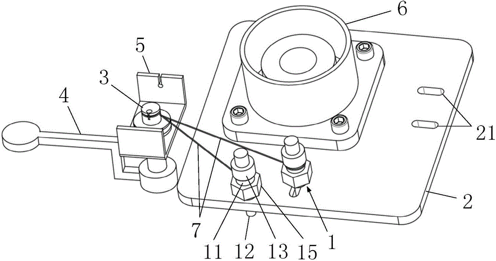
[0031] Such as figure 1 As shown, Embodiment 1 of the present invention provides a limiting mechanism for limiting the position between the first rotating body and the second rotating body that are rotatably connected. The first rotating body and the second rotating body can be the Two split-type bed boards connected by rotation, the limiting mechanism is installed on the steel frames at the sides of the two bed boards, and the limiting mechanism includes elastic positioning pin 1, limiting plate 2, hinge shaft 3 and rope 7.

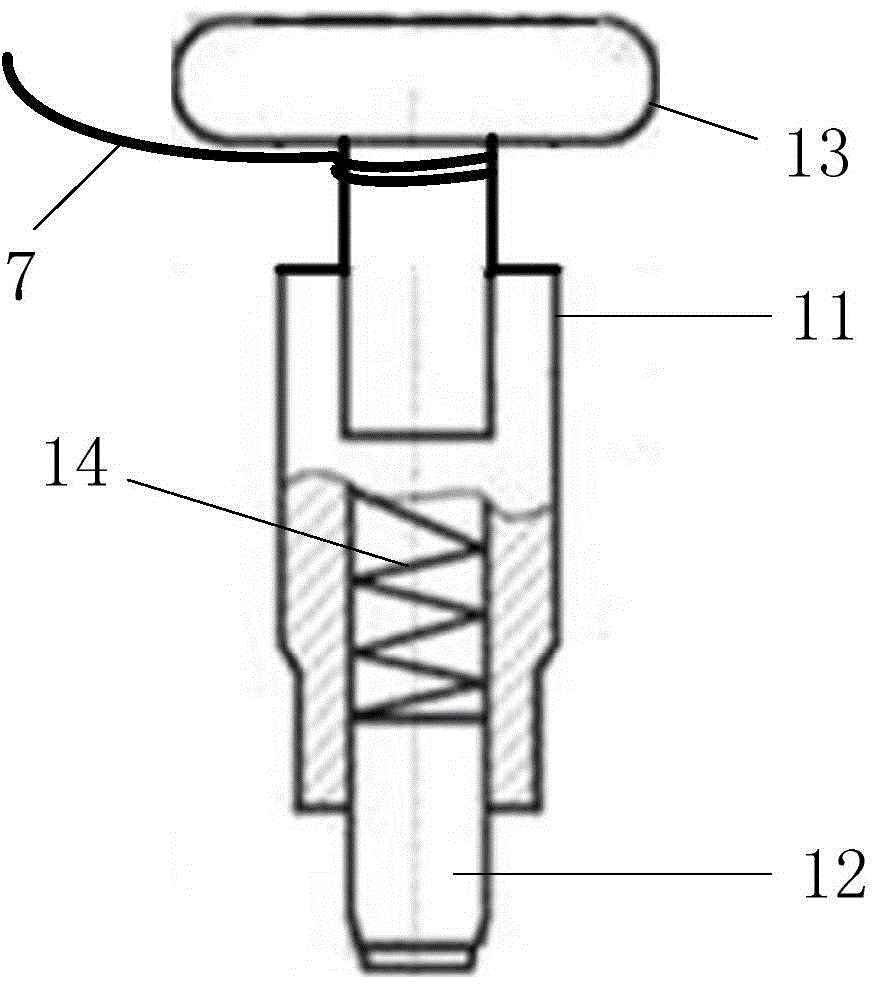
[0032] recombine figure 2 As shown, the elastic positioning pin 1 includes a shaft sleeve 11, a pin shaft 12 and a spring; the bottom of the pin shaft 12 is thicker than the middle part, the bottom of the pin shaft 12 is equivalent to the inner diameter of the shaft sleeve 11, and the bottom of the pin shaft 12 can be placed on the shaft sleeve 11 The inner sliding of the pin shaft 12 is telescopically installed on the shaft sleeve 11, that is, the bot...

Embodiment 2

[0040] The limiting mechanism provided in the second embodiment has basically the same structure as that of the first embodiment, and the similarities will not be described again. The difference lies in:

[0041] A bearing 6 is provided on the limiting plate 2, and the first rotating body is connected with the bearing 6. The first rotating body is connected to the limiting plate 2 through the bearing 6, so that the first rotating body is indirectly connected to the second rotating body. body, so that the distance between the elastic positioning pin 1 and the transition point between the first and second rotating bodies can be shortened to the greatest extent, that is, the radius of rotation of the elastic positioning pin 1 is shortened. Since the radius of rotation of the elastic positioning pin 1 is shortened, when the elastic positioning pin 1 rotates from the limiting hole 21 corresponding to one rotation orientation to the limiting hole 21 corresponding to another rotation ...

Embodiment 3

[0043] The limiting mechanism provided in the second embodiment is basically the same in structure as the second embodiment, and the similarities will not be described again. The difference lies in:

[0044] The elastic locating pin 1, the rope 7 and the limit hole 21 are correspondingly set to be multiple, that is, a plurality of elastic locating pins 1 are installed on the first swivel, and correspondingly, a plurality of elastic locating pins 1 are installed on the limiting plate 2. A plurality of position-limiting holes 21 are provided at a position corresponding to a certain rotational direction of the locating pin 1, and a plurality of ropes 7 are connected between the pin shafts 12 of the plurality of elastic positioning pins 1 and the hinge shaft 3, and one end of the plurality of ropes 7 is respectively connected to a plurality of The pin shaft 12 of the elastic positioning pin 1 is connected, and the other end is all wound around the top of the hinge shaft 3 . When t...


PUM


Abstract

The invention relates to the field of medical instruments, and provides a limiting mechanism used for limiting a first rotating body and a second rotating body which are rotationally connected. The limiting mechanism comprises elastic positioning pins, a limiting plate, a hinge shaft and ropes. Each elastic positioning pin comprises a shaft sleeve, a pin shaft and an elastic piece, wherein one end of the pin shaft penetrates through the shaft sleeve in a telescopic mode, the elastic piece is elastically connected between the pin shaft and the shaft sleeve, and the pin shaft is installed on the first rotating body through the shaft sleeve. The limiting plate is installed on the second rotating body, limiting holes are formed in the limiting plate, and the limiting holes are formed below one rotating position of the elastic positioning pins so that the pin shafts can be connected with the limiting holes in an inserted and pulled mode. The hinge shaft is installed on the first rotating body, one ends of the ropes are hinged to the hinge shaft in a surrounding mode, the other ends of the ropes are connected with the other ends of the pin shafts, the ends, connected with the hinge shaft, of the ropes are higher than the ends, connected with the pin shafts, of the ropes, and the pin shafts are automatically inserted in the limiting holes through the elastic pieces. The limiting mechanism is convenient to operate, accurate in positioning, good in stability, simple in structure and convenient to use and popularize.

Description

technical field [0001] The present invention relates to the field of medical devices, and in particular provides a limiting mechanism, and more specifically relates to a limiting mechanism for a seat or a bed. Background technique [0002] my country has a large population, accounting for about one-fifth of the world's total population. The medical device market has huge potential. The accelerated economic development has driven the upgrading of medical service demand, and the rapid economic development has led to an overall increase in the demand for health services. The gradual opening up of the medical service market has accelerated the investment of domestic and foreign capital in China's medical service industry, thereby increasing the demand for medical devices. As a relatively important part of the medical device field, medical chairs or medical beds have broad market prospects. The fixing, adjustment and limit of medical chairs or medical beds need to be completed by...

Claims


Application Information

Patent Timeline
Patent Type & Authority Applications(China)
IPC IPC(8): A61G7/05A61G5/10
Inventor 刘敏付威威郁朋陈奭郑健范梅生
Owner SUZHOU INST OF BIOMEDICAL ENG & TECH CHINESE ACADEMY OF SCI
Why Eureka
Try Eureka