A pipe forming device

A technology for forming devices and pipe fittings, applied in forming tools, feeding devices, positioning devices, etc., can solve the problems of increased labor, high manufacturing costs, inaccurate positioning, etc., to reduce labor input, avoid accuracy loss, and reduce manufacturing. cost effect

Active Publication Date: 2017-07-28
ZHENJIANG MINGCHENG PIPE IND CO LTD
View PDF7 Cites 0 Cited by
  • Summary
  • Abstract
  • Description
  • Claims
  • Application Information

AI Technical Summary

Problems solved by technology

First, because processing grooves need to be set on both sides of the pipe fittings, when the existing forming device processes the pipe fittings, one side needs to be processed first, and then the other side is processed, which results in low processing efficiency
Second, due to the sequential processing of both sides, two sets of processing devices will be required, which will impose a burden on site resources, increase labor at the same time, and cause high manufacturing costs
Third, because the pipe fitting is a special-shaped pipe fitting, the whole pipe fitting is not in the same plane space, and it has multiple bends, so it is difficult to fix and position the fixed pipe fitting, and the positioning is inaccurate. The machining accuracy is low, and the quality cannot meet the requirements

Method used


Image

  • A pipe forming device
  • A pipe forming device
  • A pipe forming device

Examples


Embodiment Construction

[0021] The present invention will be further described below in conjunction with the accompanying drawings. The following examples are only used to illustrate the technical solution of the present invention more clearly, but not to limit the protection scope of the present invention.

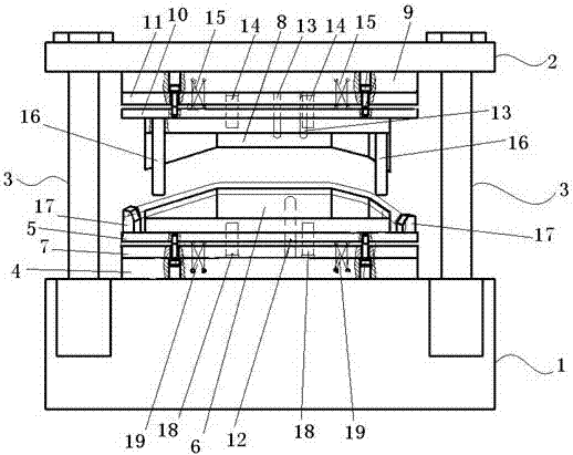
[0022] Such as figure 1 As shown, a pipe fitting forming device includes an upper base plate 2, an upper mold base 9, an upper clamping plate 11, an upper stripping plate 10, an upper mold assembly 8, a lower mold assembly 6, and a lower stripping plate arranged sequentially from top to bottom. 5. The lower splint 7, the lower mold base 4 and the workbench 1.

[0023] A lifting mechanism 3 is arranged between the workbench 1 and the upper base plate 2 , and the upper base plate 2 moves up and down through the lifting mechanism 3 .

[0024] The lower mold base 4 is fixed on the top surface of the worktable 1, the lower mold assembly 6 is fixed on the top surface of the lower stripping plate 5, ...


PUM


Abstract

The invention discloses a pipe fitting forming device, which comprises a workbench and an upper base plate arranged sequentially from top to bottom, a lifting mechanism is arranged between the workbench and the upper base plate, and the upper base plate moves up and down through the lifting mechanism; the top surface of the workbench The lower mold assembly, the lower stripping plate and the lower mold base are arranged in sequence from top to bottom; the upper mold base, the upper stripping plate and the upper mold group are arranged in sequence from top to bottom on the bottom surface of the upper base plate opposite to the top surface of the workbench pieces. Compared with the single-station, single-process processing mode, the present invention saves the time spent on re-clamping pipe fittings between processing processes, has high processing efficiency, avoids the loss of precision caused by multiple clamping, and effectively improves the processing accuracy. , fully meet the quality requirements.

Description

technical field [0001] The invention relates to a pipe fitting forming device, which belongs to the field of pipe fitting forming machinery. Background technique [0002] In the prior art, pipe fittings are used more and more widely, and pipe fittings are also an indispensable part in auto parts. The wiper motor on the car usually needs pipe fittings to complete the assembly work, and the pipe fitting will be used as a support tube to support and fix the wiper motor. The two ends of the pipe fitting used as the support pipe will be connected and fixed with the wiper gearbox, and the middle part needs to be grooved to position and fix the wiper motor. This groove is opened on both symmetrical sides of the middle part of the pipe fitting. groove, and on the other side is a slightly larger groove. These three grooves are fixed with the connection device of the wiper head and determine the position of the motor in space. [0003] There are mainly three problems in the process...

Claims


Application Information

Patent Timeline
Patent Type & Authority Patents(China)
IPC IPC(8): B21D17/02B21D43/00B21D37/10
Inventor 孙云飞胥青
Owner ZHENJIANG MINGCHENG PIPE IND CO LTD
Why Eureka
Try Eureka