Automatic lifting ring separation mechanism

An automatic separation and ring separation technology, which is applied in packaging and other directions, can solve the problems of uncontrollable falling state of the lifting ring, low efficiency of manual installation, poor overall stability, etc., and achieve the effect of stable and reliable separation process, stable cutting, and not easy to squeeze

Active Publication Date: 2015-05-13
NINGBO CHANGRONG BREWING EQUIP
View PDF7 Cites 2 Cited by
  • Summary
  • Abstract
  • Description
  • Claims
  • Application Information

AI Technical Summary

Problems solved by technology

At present, most enterprises install the lifting rings on the bottle body manually by workers. Manual installation is inefficient and labor-intensive. At present, there are also equipment for automatically installing lifting rings. The rings are separately separated in turn and matched with the bottle body, so how to stably separate the lifting ring is the focus and difficulty of realizing the automatic assembly of the lifting ring. A lifting ring assembly device, including a frame and a conveying part, a material storage part, a sub-ring part and a pressing ring part arranged on the frame, the material storage part, the sub-ring part and the pressing ring part are formed along the conveying direction of the bottle Set up in sequence from front to back, the storage part, sub-ring part and pressure ring part are set above the conveying part, the sub-ring part corresponds to the lower end of the storage part, and is used to install the lifting ring on the bottle container
This kind of lifting ring assembly device realizes the ring splitting action through the reverse reciprocating motion of the middle split ring plate and the side split ring plate. The middle split ring plate needs to be directly inserted into the gap between the two lifting rings, and the bottom lifting ring is separated directly. Falling, the falling state of the lifting ring is uncontrollable, the overall stability is poor, and some lifting rings have a small gap after overlapping, it is difficult to insert the front of the lifting ring accurately into the gap between the lifting rings, which will cause some bottles to be missing. ring

Method used


Image

  • Automatic lifting ring separation mechanism
  • Automatic lifting ring separation mechanism
  • Automatic lifting ring separation mechanism

Examples


Embodiment Construction

[0021] The present invention will be further described below in conjunction with accompanying drawing and specific embodiment:

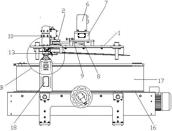
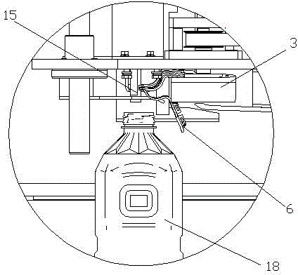
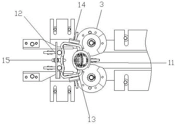
[0022] Such as figure 1 and figure 2 A lifting ring automatic separation mechanism shown includes a base plate 1, and the left end of the base plate is provided with a sub-ring wheel assembly 2, such as Figure 4 As shown, the sub-ring wheel assembly 2 includes two symmetrical sub-ring wheels 3 and a connecting seat 4, the sub-ring wheel is provided with a rotating shaft 5, the rotating shaft is connected to the connecting seat 1 in rotation, the connecting seat is connected to the base plate, and the base plate 1 is also provided with There is a motor 6 and a gear box 7 connected to the motor. The gear box is provided with two parallel output shafts with the same speed and opposite directions. The two output shafts are respectively connected to the two rotating shafts through a synchronous wheel 8 and a synchronous belt 9. ,Such as Figure 5 As ...


PUM


Abstract

The invention relates to the technical field of lifting ring assembling and discloses an automatic lifting ring separation mechanism. The automatic lifting ring separation mechanism comprises a base plate, a ring separation assembly is arranged at one end of the base plate and comprises two symmetric ring separating wheels and a connecting seat, rotating shafts are arranged on the ring separating wheels, the rotating shafts are rotationally connected with the connecting seat, the base plate is further provided with a motor and a gearbox connected with the motor, the gearbox is provided with two parallel output shafts which are the same in rotating speed and opposite in rotating direction, and the two output shafts are connected with the two rotating shafts through synchronous wheels and synchronous belts. Wedge-shaped ring separating notches are formed in one sides of the upper ends of the ring separating wheels, ring separating grooves distributed in the tangential direction are formed below the wedge-shaped ring separating notches, the lower side faces of the wedge-shaped ring separating notches extend towards the lower ends of the ring separating wheels along the circumferential faces to form separating slopes, and the end, close to the ring separating wheel assembly, of the base plate is further provided with a ring lifting pre-positioning mechanism. Thus, the automatic lifting ring separation mechanism has the advantages that lifting rings can be separated accurately, stably and rapidly, and bottle bodies can be assembled with the lifting rings in a one-to-one correspondence mode.

Description

technical field [0001] The invention relates to the technical field of lifting ring assembly, in particular to a lifting ring automatic separation mechanism. Background technique [0002] Bottle containers with large capacity, such as large bottles of mineral water, edible oil, beverage bottles, etc., are not easy to carry due to their heavy weight, so a hand-held lifting ring will be installed at the neck of the bottle. The lifting ring generally includes a buckle part and a hand-held part. , the fastening part is pressed into the bottleneck to realize the connection, and the handle part is convenient for carrying. At present, most enterprises install the lifting rings on the bottle body manually by workers. Manual installation is inefficient and labor-intensive. At present, there are also equipment for automatically installing lifting rings. The rings are separately separated in turn and matched with the bottle body, so how to stably separate the lifting ring is the focus...

Claims


Application Information

Patent Timeline
Patent Type & Authority Applications(China)
IPC IPC(8): B65B61/14
CPCB65B61/14
Inventor 郑卫忠祝闽周东陈凯
Owner NINGBO CHANGRONG BREWING EQUIP
Why Eureka
Try Eureka