Improved skein dyeing machine

A hank dyeing machine, an improved technology, is applied in the directions of spray/jet textile material processing, textile material processing equipment configuration, etc., which can solve the problems of deformation of the liquid spray pipe, high manufacturing cost, and very high sealing requirements, and meet the sealing requirements. Reduction, low manufacturing cost, effect of preventing deformation

Active Publication Date: 2015-05-13
刘骏
View PDF6 Cites 8 Cited by
  • Summary
  • Abstract
  • Description
  • Claims
  • Application Information

AI Technical Summary

Problems solved by technology

[0002] Existing spray type skein dyeing machine, it generally is that a liquid spray pipe is hinged on the side wall of frame, and skein is placed on the liquid spray pipe, rotates while passing through liquid spray pipe, generally dye liquor is sprayed from the spray pipe. There is a through hole on the side wall of the liquid pipe for dyeing. Only one end of the liquid spray pipe is hinged, and the other end is not supported. After a long time, the liquid spray pipe is easily deformed and damaged
[0003] At the same time, the existing liquid spray pipe needs to rotate while spraying liquid, and the infusion pipe needs to be connected with the liquid spray pipe. Since the liquid infusion pipe does not move, the liquid spray pipe needs to rotate, so the requirements for its sealing are very high. Its manufacturing cost is high and its structure is relatively complex

Method used


Image

  • Improved skein dyeing machine
  • Improved skein dyeing machine

Examples


Embodiment Construction

[0016] The present invention will be described in detail below in conjunction with accompanying drawings and specific preferred embodiments, so that the advantages and features of the present invention can be more easily understood by those skilled in the art. range is limited.

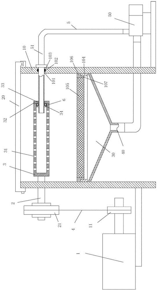
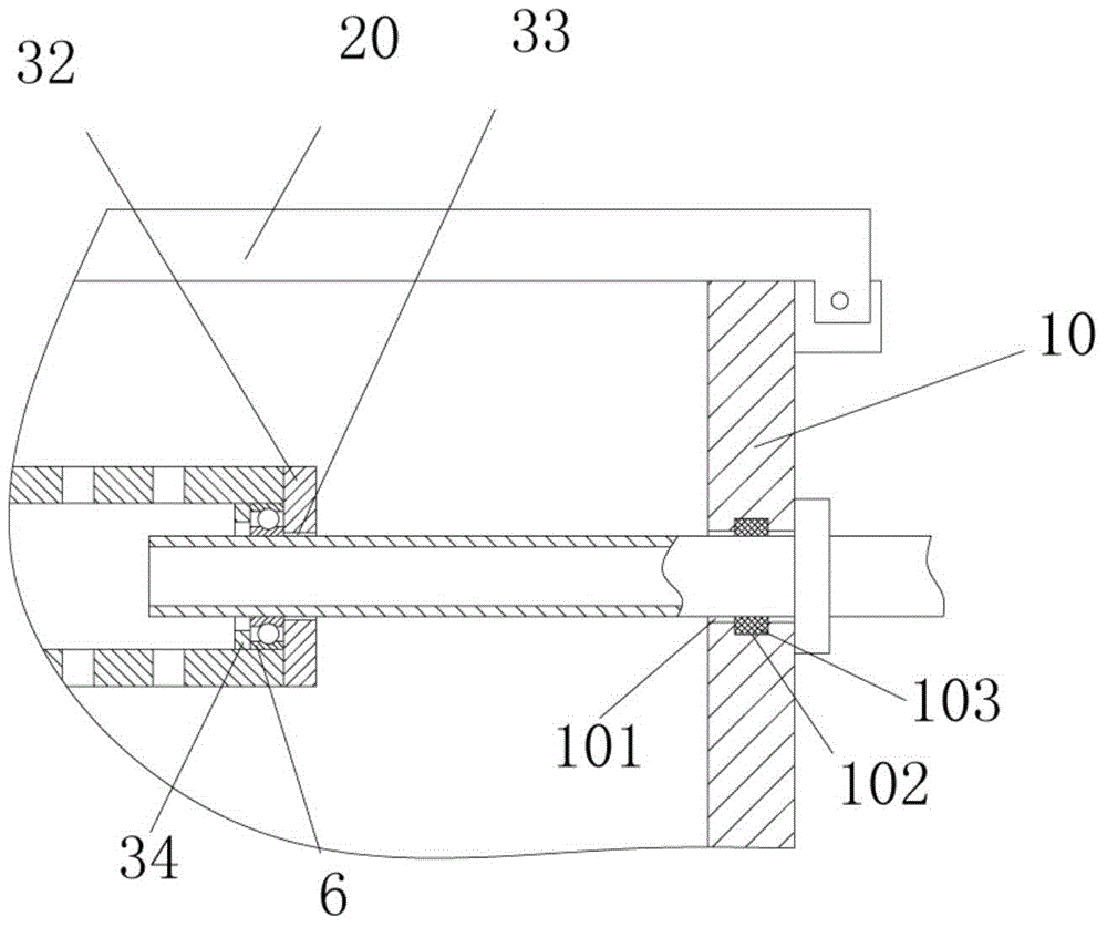
[0017] Examples, see e.g. Figure 1 to Figure 2 Shown, a kind of improved skein dyeing machine comprises frame 10 and machine cover 20, and one end of machine cover 20 is hinged on the top of frame 10, and machine cover 20 covers on frame 10, and described frame 10 Rotating motor 1 is fixed on the left side of the rotating motor 1, output sprocket 11 is fixed on the output shaft of rotating motor 1, and rotating shaft 2 is hinged on the top of the left side plate of frame 10, and the front end of rotating shaft 2 stretches in the frame 10 and The liquid spray pipe 3 is fixed, the part of the rotating shaft 2 outside the frame 10 is fixed with a transmission sprocket 21, and the chain 4 is tensioned b...


PUM


Abstract

The invention discloses an improved skein dyeing machine. The skein dyeing machine comprises a rack and a machine cover, wherein the machine cover covers the rack; a rotating motor is fixed on the left side of the rack; an output chain wheel is fixed on an output shaft of the rotating motor; a rotating shaft is hinged to the upper part of a left side plate of the rack; the front end of the rotating shaft stretches into the rack and is fixed with a liquid spraying pipe; a driving chain wheel is fixed on the part, outside the rack, of the rotating shaft; a chain is tensioned between the driving chain wheel and the output chain wheel; a tapered dye trough is formed in the bottom of the rack; a liquid outlet pipe is arranged at the bottom of the tapered dye trough; a recycling pump is fixed on the right side of the rack; the liquid outlet pipe is communicated with a liquid inlet of the recycling pump through a connecting pipe; the liquid outlet of the recycling pump is connected with a liquid conveying pipe; the upper end of the liquid conveying pipe passes through a right side plate of the rack, and stretches into an inserting hole of the right end of the liquid spraying pipe. According to the skein dyeing machine, the liquid spraying pipe and the liquid conveying pipe are arranged on two side walls of the rack respectively, and the end parts of the two pipes are communicated with each other, so that the fact that both ends of the liquid spraying pipe are supported is guaranteed, so as to prevent deformation.

Description

Technical field: [0001] The invention relates to the technical field of textile printing and dyeing equipment, in particular to an improved skein dyeing machine. Background technique: [0002] Existing spray type skein dyeing machine, it generally is that a liquid spray pipe is hinged on the side wall of frame, and skein is placed on the liquid spray pipe, rotates while passing through liquid spray pipe, generally dye liquor is sprayed from the spray pipe. The through hole that has on the side wall of liquid pipe is discharged to carry out dyeing, and its liquid spray pipe has only one end to be hinged, and the other end has not received supporting effect, and time is long, easily makes liquid spray pipe deformation and damage. [0003] At the same time, the existing liquid spray pipe needs to rotate while spraying liquid, and the infusion pipe needs to be connected with the liquid spray pipe. Since the liquid infusion pipe does not move, the liquid spray pipe needs to rotat...

Claims


Application Information

Patent Timeline
Patent Type & Authority Applications(China)
IPC IPC(8): D06B1/02D06B23/20
CPCD06B1/02D06B23/20
Inventor 方永强
Owner 刘骏
Why Eureka
Try Eureka