Target material assembly and manufacturing method thereof

A manufacturing method and technology for a target material, which are applied in the field of target material components and their manufacturing, can solve the problems of affecting the frequency of target replacement, high replacement frequency of target components, affecting the efficiency of the sputtering process, etc., so as to avoid adverse effects, process Efficiency improvement and process cost reduction effect

Inactive Publication Date: 2019-02-26
KONFOONG MATERIALS INTERNATIONAL CO LTD
View PDF7 Cites 11 Cited by
  • Summary
  • Abstract
  • Description
  • Claims
  • Application Information

AI Technical Summary

Problems solved by technology

The length of target service life will affect the frequency of target replacement, thus affecting the efficiency of the sputtering process
[0005] However, the service life of target components in the prior art is relatively short, resulting in high frequency of replacement of target components, which affects the efficiency of the sputtering process and increases the cost of the process

Method used


Image

  • Target material assembly and manufacturing method thereof
  • Target material assembly and manufacturing method thereof
  • Target material assembly and manufacturing method thereof

Examples


Embodiment Construction

[0022] It can be seen from the background art that the service life of the target component is short. Combining with the structure of a target component, the reasons for its short service life are analyzed.

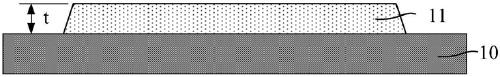
[0023] refer to figure 1 , shows a schematic structural view of a target assembly. The target assembly includes a target 11 and a back plate 10 that is welded to the target 11 .

[0024] During the sputtering process, the atoms of the material in the target 11 collide with the charged particles and overflow. The used thickness of the target component refers to the thickness of the target 11 that the material will be sputtered during sputtering, that is, in During the sputtering process, the thickness of the target material 11 that is consumed due to sputtering.

[0025] In order to prevent the back plate 10 from being damaged by sputtering, and to avoid sputtering to the back plate 10 from affecting the performance of the deposited film layer, the thickness of the targ...


PUM

PropertyMeasurementUnit
thicknessaaaaaaaaaa
thicknessaaaaaaaaaa
thicknessaaaaaaaaaa

Abstract

The invention provides a target material assembly and a manufacturing method thereof. The manufacturing method comprises the following step: providing a target material and a back plate capable of bonding with the target material in a welded manner so as to form the target material assembly, wherein the thickness of the target material accounts for at least 60% of the thickness of the target material assembly. According to the invention, the thickness of the target material accounts for at least 60% of the thickness of the target material assembly; thus, compared with a scheme that the thickness of the target material accounts for a smaller proportion of the thickness of the target material assembly, the target material assembly provided by the invention has the following advantages: the thickness of the target material can be increased under the condition that the thickness of the target material assembly is unchanged, and the part of the target material for sputtering is correspondingly increased, so the service life of the target material assembly is effectively prolonged; the replacement frequency of the target material assembly is effectively reduced; improvement of process efficiency and reduction of process cost can be easily realized; meanwhile, the thickness of the target material assembly can remain unchanged, so a sputtering machine bench does not need to adjust thespacing between the target material and a product about to undergo film formation (such as a wafer), and adverse effects on the initial sputtering rate and film-forming uniformity of the target material assembly are avoided.

Description

technical field [0001] The invention relates to the field of semiconductor manufacturing, in particular to a target component and a manufacturing method thereof. Background technique [0002] In the semiconductor manufacturing process, it is often necessary to form various film layers. The magnetron sputtering process has become the most excellent substrate coating process due to its advantages of high sputtering rate, low substrate temperature rise, good film-substrate bonding force, excellent coating uniformity and strong controllability, and has become a semiconductor A widely used film-forming process in manufacturing. [0003] The magnetron sputtering process is one of the physical vapor deposition processes. Specifically, a closed magnetic field parallel to the target surface is added in dipole sputtering, and the secondary electrons are confined to a specific area of ​​the target surface by means of the orthogonal electromagnetic field formed on the target surface t...

Claims


Application Information

Patent Timeline
Patent Type & Authority Applications(China)
IPC IPC(8): C23C14/34C23C14/35C23C14/14
Inventor 姚力军潘杰相原俊夫王学泽刘霞昝小磊
Owner KONFOONG MATERIALS INTERNATIONAL CO LTD
Why Eureka
Try Eureka