Asynchronous starting type permanent magnetic synchronizing motor of double-rotor structure
A permanent magnet synchronous and asynchronous starting technology, applied in the field of motors, can solve the problems of reducing the risk of permanent magnet demagnetization, increasing the inductance of the motor, and reducing the starting current of the motor, so as to reduce the risk of demagnetization, increase the inductance, and reduce the starting effect of current
- Summary
- Abstract
- Description
- Claims
- Application Information
AI Technical Summary
Problems solved by technology
Method used
Image

Examples
Embodiment 1
[0022] Embodiment 1 Radial air gap magnetic field asynchronous start permanent magnet synchronous motor
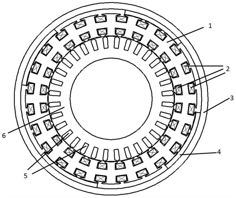
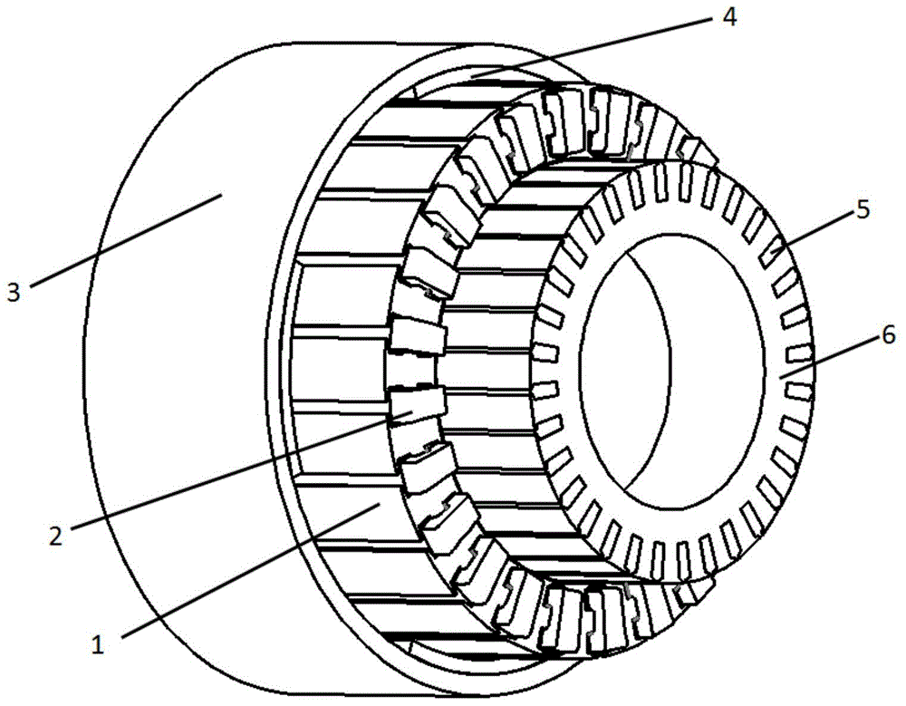
[0023] Fig. 1 shows the schematic diagram of a specific embodiment of the asynchronous start permanent magnet synchronous motor of double-rotor structure of the present invention, wherein Fig. 1 (a) is a transverse sectional view, and Fig. 1 (b) is a three-dimensional structural schematic diagram. The first embodiment is a radial air gap magnetic field motor topology. At this time, the first rotor core is the outer rotor core 3, the second rotor core is the inner rotor core 6, the stator is located in the middle of the inner and outer rotors, and the stator There are upper and lower layers of slots on the iron core 1, and the stator windings 2 are placed respectively. Among them, the placement positions of both sides of the stator winding 2 can be varied, such as placing in two radially upper and lower slots, tangentially adjacent two slots, or in two slots with a certain ...
Embodiment 2
[0026] Embodiment 2 Axial air gap magnetic field asynchronous start permanent magnet synchronous motor
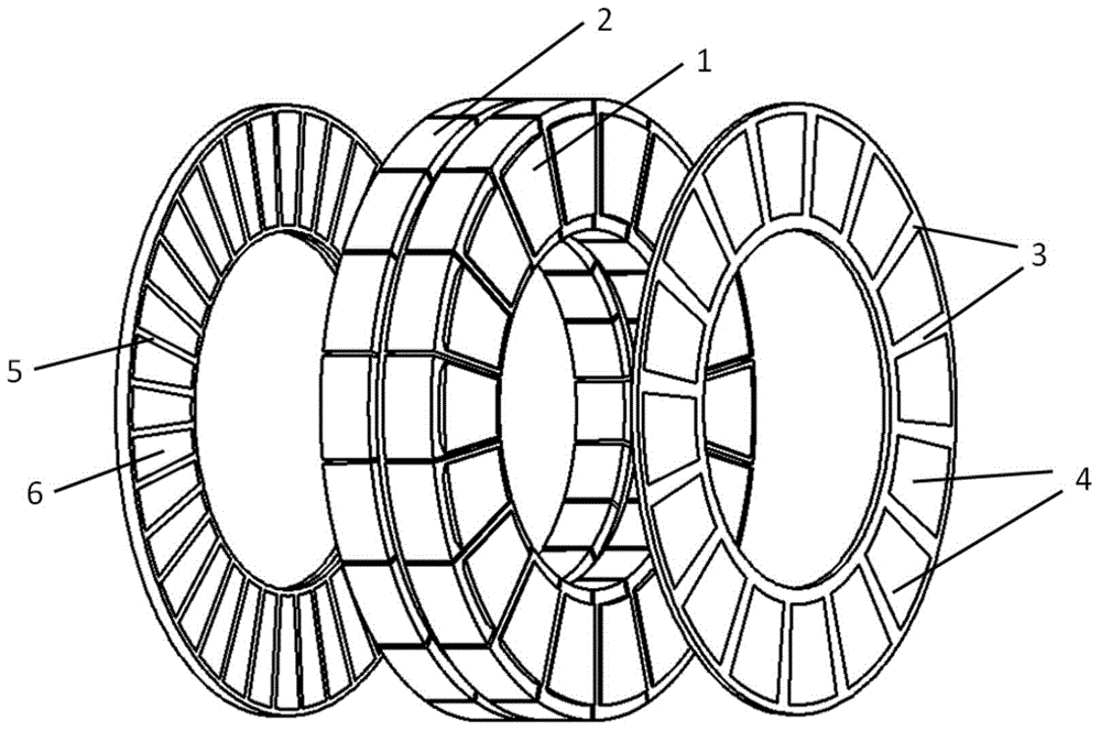
[0027] figure 2 Shown is the schematic diagram of another specific embodiment of the asynchronous start permanent magnet synchronous motor of the double rotor structure of the present invention, wherein figure 2 It is a schematic diagram of a three-dimensional structure. This embodiment is an axial air gap magnetic field disk motor topology, such as figure 2 As shown, the stator is located between the inner and outer rotors, and the stator winding 2 is arranged on the stator core 1 . Wherein, the placement positions of the two sides of the stator winding 2 can be changed in many ways, such as crossing two slots tangentially or crossing two slots axially, the figure shown is only one of them.
[0028] A starting winding 5 is embedded on the outer surface of the inner rotor iron core 6 , and a permanent magnet 4 is pasted on the inner surface of the outer rotor iron core 3...
PUM
 Abstract
Description
Claims
Application Information
 - R&D
- Intellectual Property
- Life Sciences
- Materials
- Tech Scout
- Unparalleled Data Quality
- Higher Quality Content
- 60% Fewer Hallucinations
Browse by: Latest US Patents, China's latest patents, Technical Efficacy Thesaurus, Application Domain, Technology Topic, Popular Technical Reports.
© 2025 PatSnap. All rights reserved.Legal|Privacy policy|Modern Slavery Act Transparency Statement|Sitemap|About US| Contact US: help@patsnap.com