Symmetrical permanent-magnet linear synchronous motor

A permanent magnet synchronous linear, symmetrical technology, applied in electrical components, electromechanical devices, electric components, etc., can solve the problems of unstable operation, eddy current effect, small suspension height, etc., to simplify the control equipment, improve the utilization rate, Avoid the effect of heat

Active Publication Date: 2015-05-13
江苏希太芯科技有限公司
View PDF10 Cites 16 Cited by
  • Summary
  • Abstract
  • Description
  • Claims
  • Application Information

AI Technical Summary

Problems solved by technology

[0004] For many types of linear motors, the primary is only placed on one side. For such a structure of unilateral linear motors, the biggest feature is that there is a large normal suction between the primary and the primary, and the thrust is about About 10 times of that, which will lead to unstable operation of the unilateral linear motor
For most linear motors, the levitation force is the repulsion or suction force of the electromagnet: the repulsion-floating linear motor uses electromagnetic coils to induce mutual repulsion, and at the same time, it will generate eddy current effects, resulting in a large amount of heat generated by the system, which requires a cooling device. Due to the inability to accurately control the levitation force, the operation is unstable, and a strong magnetic field is also generated at the same time. The impact on the human body and other environments is not clear. The resistance of the linear motor is large when it accelerates, and it needs to provide auxiliary levitation force when it is stationary and accelerating. , need to add auxiliary current compensation circuit,
The suction-floating linear motor adopts a U-shaped structure, and the suspension height is very small. It has high requirements for the machining accuracy of the track and the decoration work. The mover must have an excitation power supply, resulting in a large and inconvenient running mover.

Method used


Image

  • Symmetrical permanent-magnet linear synchronous motor
  • Symmetrical permanent-magnet linear synchronous motor
  • Symmetrical permanent-magnet linear synchronous motor

Examples


Embodiment Construction

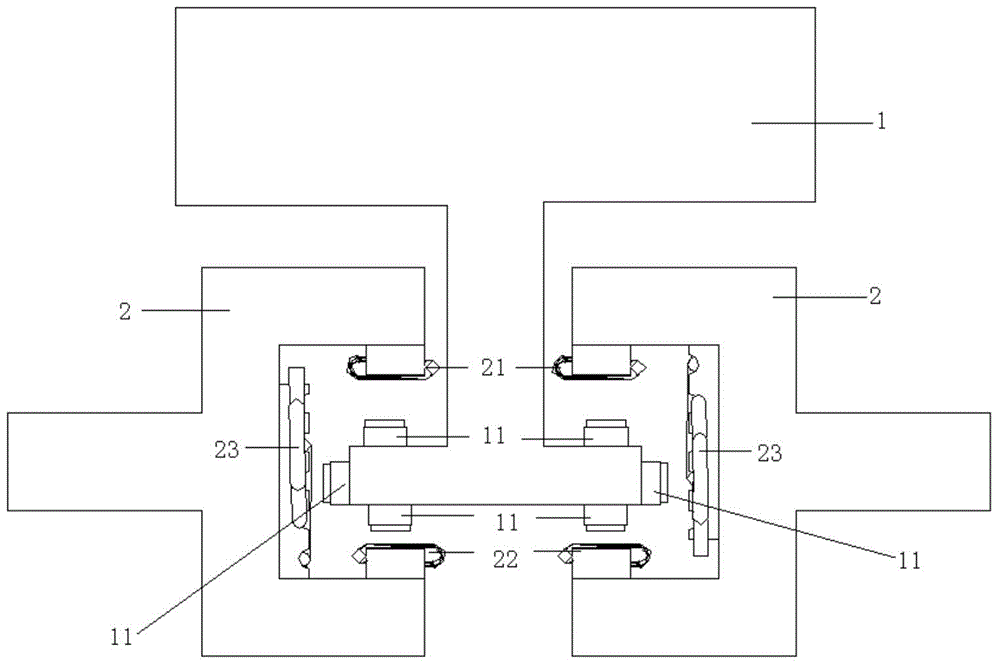
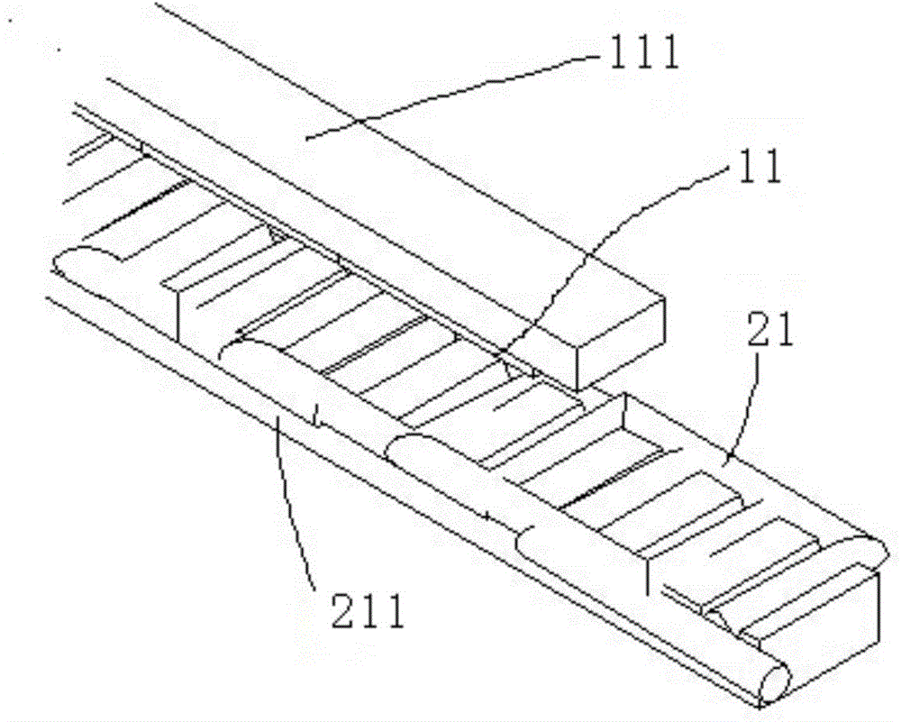
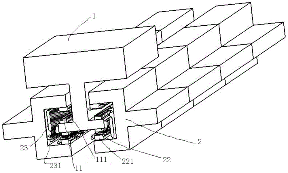
[0025] refer to Figure 1 to Figure 3 , a symmetrical permanent magnet synchronous linear motor, including a mover 1 and a number of stator guide rails 2 symmetrically arranged on both sides of the mover, and a plurality of the stator guide rails 2 constitute the movement track of the mover; the mover 1 Three sets of arrayed permanent magnets 11 are symmetrically arranged on both sides of the bottom, the stator guide rail 2 has a U-shaped structure, and the opening ends of the U-shaped structure of the stator guide rails on both sides are opposite; the opening of the U-shaped structure The upper and lower positions of the end are fixedly installed with traction force coils 21, 22 with the same structure, and the inner side of the bottom of the U-shaped structure is fixedly installed with a levitation force coil 23;

[0026] The levitation force coil 23 located inside the bottom of the U-shaped structure interacts with the arrayed permanent magnet 11 located at the correspondin...


PUM


Abstract

The invention discloses a symmetrical permanent-magnet linear synchronous motor. The motor comprises a rotor and a plurality of stator guide rails symmetrically arranged on both sides of the rotor, wherein the plurality of stator guide rails forms a movement track where the rotor moves; both sides of the bottom of the rotor are symmetrically provided with three groups of array permanent magnets respectively, each stator guide rail includes an U-shaped structure, and open ends of the U-shaped structures of the stator guide rails on both sides are oppositely arranged; the upper and lower positions of the open ends of the U-shaped structures are respectively fixed with a traction force coil, and a suspension force coil is fixedly installed inside the bottom of the U-shaped structure; the suspension force coil inside the bottom of the U-shaped structure interacts with the array permanent magnet at the corresponding position of the bottom of the rotor, and the traction force for upwardly suspending the rotor and the normal force are simultaneously generated; the suspension force coils on the stator guide rails symmetrically arranged on two sides of the rotor interact with the normal force generated by the array permanent magnet, so that the rotor of the linear motor always moves at the center of the guide rail.

Description

technical field [0001] The invention relates to a symmetrical permanent magnet synchronous linear motor. Background technique [0002] High-speed and high-precision linear motion is generally driven by linear motors, such as maglev trains, material conveyors, advanced machine tools, etc. In 1840, the British Whiston invented the world's first linear motor, but due to theoretical and technical defects, it was not until the middle of the 20th century that the linear motor entered a new stage of development. [0003] The linear motor servo system is a power device that directly converts electrical energy into mechanical energy for linear motion. It does not have an intermediate conversion link for a rotating motor, and can effectively overcome the traditional conversion mechanism's large volume, low precision, low efficiency, slow response, and loud noise. And many other shortcomings. The linear motor can be regarded as a rotary motor that is planed along the radial direction...

Claims


Application Information

Patent Timeline
Patent Type & Authority Applications(China)
IPC IPC(8): H02K41/03
Inventor 史伟民许守金杨亮亮葛宏伟欧阳博刘权庆
Owner 江苏希太芯科技有限公司
Why Eureka
Try Eureka