Line arrester

A technology for line arresters and overhead lines, which is applied to circuits, circuit devices, overvoltage protection resistors, etc., and can solve problems such as increasing the structural length of line arresters

Inactive Publication Date: 2015-05-13
SIEMENS AG
View PDF7 Cites 2 Cited by
  • Summary
  • Abstract
  • Description
  • Claims
  • Application Information

AI Technical Summary

Problems solved by technology

However, this increases the structural length of the line arrester

Method used


Image

  • Line arrester
  • Line arrester
  • Line arrester

Examples


Embodiment Construction

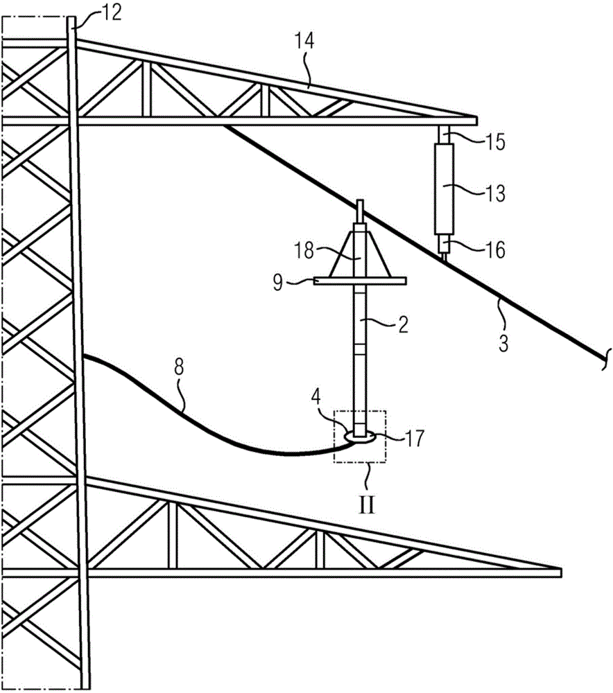
[0024] figure 1 It represents the overhead line 3, which is fixed on the iron tower cantilever 14 of the circuit iron tower 12 by means of an insulator 12. The overhead line 3 is here an electrical conductor carrying high or medium voltage. The overhead line 3 is suspended on the circuit tower 12 in the air. Usually several such electrical conductors are suspended on the circuit tower 12 , which can, for example, assume different phases. Circuit tower 12 is normally at ground potential. In order to insulate the electrically conductive overhead line from ground potential, the overhead line 3 is suspended via an insulator 13 at a distance from the tower arm 14 . The insulator 13 is fixed at one end to the tower cantilever 14 by means of a fitting 15 and has a suspension fitting 16 for the overhead line 3 at the other end.

[0025] Without other protective measures, there is a danger within the circuit tower 12 or the overhead line 3 when lightning strikes that one of the ins...


PUM


Abstract

The arrester has a discharge column hangingly fastened to an overhead line such that the column performs an oscillating movement. A corona ring (4) is connected to the column and arranged at a free end of the column. The corona ring comprises a movement channel (5) i.e. annular duct. A balancing mass (6) is arranged in the movement channel, and moves along the movement channel against a deflection direction in an event of deflections of the arrester from a resting position. The mass comprises solid or liquid components, where solid components are designed as bulk from roll or sliding elements. The liquid components are selected from water and glycerol or a salt solution or a sugar solution or oils, or ester or an ionic liquid.

Description

technical field [0001] The invention relates to a line arrester according to patent claim 1 . Background technique [0002] In regions with a high density of lightning strikes on the ground, overhead lines present a particularly high risk in exposed locations, where lightning strikes inside towers or overhead lines can cause serious failures in the power supply network. The consequence is often a brief blackout or even a short circuit between phases of different systems. [0003] Line arresters are meant to be an economical and feasible way to prevent or effectively reduce the occurrence of such problems. This line arrester is installed on the iron tower parallel to the insulator. Here, one end of the line arrester is connected to the overhead line leading the high or medium voltage. The other end on the ground side is connected to a ground cable at ground potential, for example to a circuit pylon which is itself grounded. If an overvoltage occurs in the overhead line, f...

Claims


Application Information

Patent Timeline
Patent Type & Authority Applications(China)
IPC IPC(8): H01C7/12H02H9/04
CPCH01C7/12H01T19/02H02G7/00H02H9/04
Inventor M.苏利泽I.戈特沙尔克
Owner SIEMENS AG
Why Eureka
Try Eureka