
Forward extrusion forging apparatus and forward extrusion forging method

An extrusion direction and extruded technology, applied in forging/pressing/hammer devices, manufacturing tools, metal extrusion, etc., can solve the confusion of orientation, differences in ease of extrusion, and difficulty in manufacturing high anisotropic rare earths Magnets, etc., to achieve the effects of uniform extrusion, suppression of strain distribution, and suppression of uneven strain distribution

Inactive Publication Date: 2015-05-20
TOYOTA JIDOSHA KK
View PDF6 Cites 2 Cited by
  • Summary
  • Abstract
  • Description
  • Claims
  • Application Information

AI Technical Summary

Problems solved by technology

Therefore, even with this forging device, it is difficult to solve the problem of the existing forward extrusion method of the related art, that is, it is difficult to manufacture a rare earth magnet with high anisotropy, because the central part of the sintered compact body is in the sintered compact body The outer peripheral part of the compact body is extruded by the punch before being extruded, and as a result, orientation disorder occurs in the compact body due to the difference in the ease of extrusion between the peripheral part and the central part

Method used


Image

  • Forward extrusion forging apparatus and forward extrusion forging method
  • Forward extrusion forging apparatus and forward extrusion forging method
  • Forward extrusion forging apparatus and forward extrusion forging method

Examples


Embodiment 1

[0063] (forward extrusion forging method in embodiment 1) Figure 3A and 3B so Figure 3A and Figure 3B The order of is showing the flowchart of the forward extrusion forging method according to Embodiment 1 of the present invention.

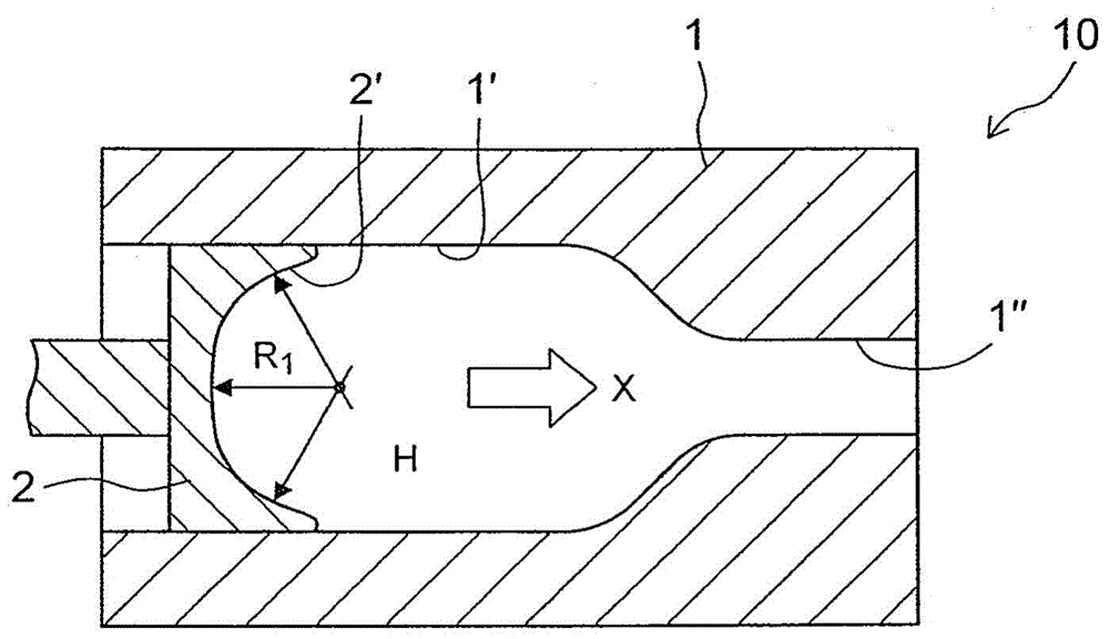
[0064] First, if Figure 3A shown, ready figure 1 The forging device 10 is shown, and the workpiece W is placed in the hollow portion H of the die 1 of the forging device 10 (first step).

[0065] Next, if Figure 3B As shown, in a state where the inside of the hollow portion H is heated to a predetermined temperature, the punch 2 is slid in the hollow portion H, and the workpiece W is extruded forward to be forged by the extrusion surface 2' of the punch 2. As a result, producing Figure 4 The forged product shown is WT (second step).

[0066] During extrusion by the punch 2, the outer peripheral portion of the workpiece W receives shear friction F from the inner peripheral portion 1' of the die 1 and is difficult to extrude smoothly tha...

Embodiment 2

[0075] (forward extrusion forging method in embodiment 2) Figure 7A and 7B so Figure 7A and Figure 7B The sequence of 1 is a flow chart showing the forward extrusion forging method according to Embodiment 2 of the present invention, that is, the relay extrusion forging method in which a plurality of forged products are manufactured while being continuously added.

[0076] First, if Figure 7A shown, ready figure 1 The forging device 10 is shown, and the workpiece W is placed in the hollow part H of the die 1 of the forging device 10, and the punch 2 is slid. As a result, the first forged product WT1 is produced (first and second steps). Next, the punch 2 is returned backward, and another workpiece W is placed in the hollow portion H. As shown in FIG.

[0077] Next, the workpiece W is extruded forward to be forged by sliding the punch 2 again, and the second forged product WT2 is continuously added behind the first forged product WT1 (third step).

[0078] Here, an ar...


PUM

PropertyMeasurementUnit
sizeaaaaaaaaaa
sizeaaaaaaaaaa
sizeaaaaaaaaaa

Abstract

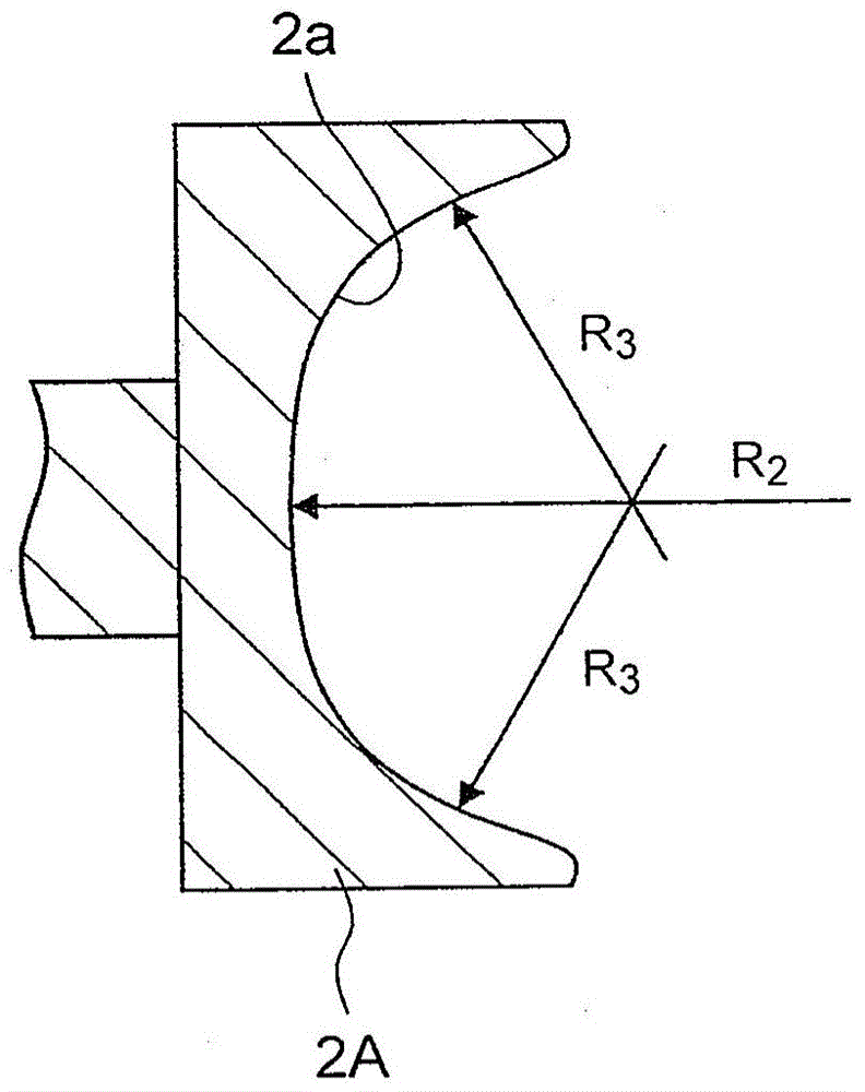
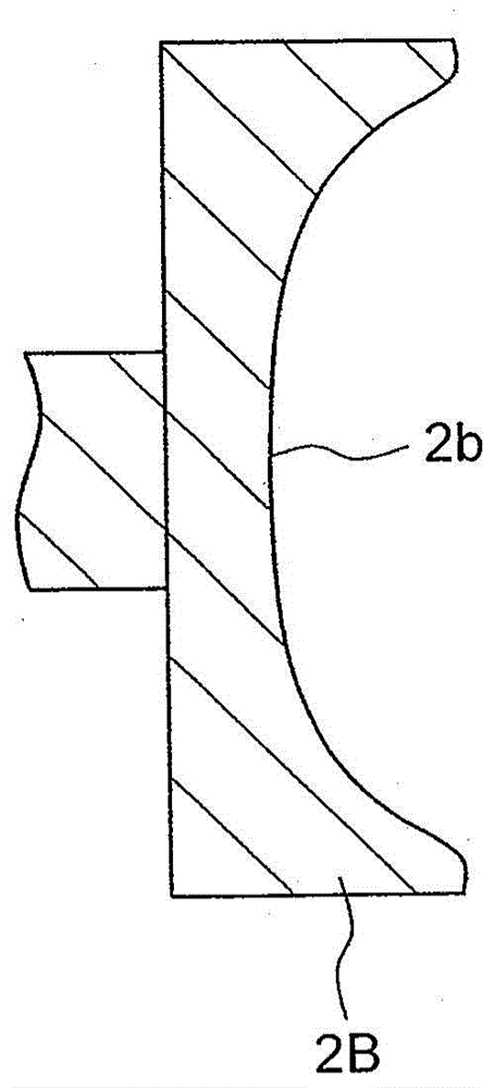
A forward extrusion forging apparatus includes: a die having a hollow portion whose diameter is reduced at an intermediate position; and a punch that is positioned behind a workpiece placed in the hollow portion, slides in the hollow portion, and extrudes the workpiece ahead of the hollow portion so that the workpiece is forged. An extruding surface of the punch, which extrudes the workpiece, is recessed in a direction opposite an extruding direction in a manner such that a center portion of the extruding surface is most recessed.

Description

technical field [0001] The invention relates to a forward (forward) extrusion forging device and a forward extrusion forging method. Background technique [0002] In hot forging, there are roughly two processing forms. One of the two processing methods is a method of producing a compact body using so-called backward extrusion (a compact body is produced while extruding the target material in the direction opposite to the extrusion direction of the punch), which includes: placing the material in the die; and extruding a part of the target material into the hollow portion of the extrusion punch while squeezing the target material with the extrusion punch to reduce its thickness. The other of the two processing methods is a method of producing a compact body using so-called forward extrusion (a compact body is produced while extruding a target material in the extrusion direction of a punch), which includes: placing in a die having a hollow; and extruding a part of the target ...

Claims


Application Information

Patent Timeline
Patent Type & Authority Applications(China)
IPC IPC(8): B21J5/02B21J13/02H01F41/02H01F1/057
CPCB21C25/02B21C26/00B22F3/003B22F3/17B22F3/20B22F2999/00C22C2202/02B21J5/022B21J13/02
Inventor 小渊大一期崎大辅保科荣介
Owner TOYOTA JIDOSHA KK
Learn More