Thumb near-knuckle force feedback detection driving device

A technology of feedback detection and driving device, applied in the field of data gloves, can solve the problems of expensive force feedback data gloves, difficult maintenance, and complex systems

Inactive Publication Date: 2015-05-20
苏茂
View PDF5 Cites 2 Cited by
  • Summary
  • Abstract
  • Description
  • Claims
  • Application Information

AI Technical Summary

Problems solved by technology

[0003] The purpose of the present invention is to solve the disadvantages of the existing force feedback data gloves, such as high price, complex system, and difficult maintenance, and proposes a combination of an external angle sensor and a joint two-way active drive device,

Method used


Image

  • Thumb near-knuckle force feedback detection driving device
  • Thumb near-knuckle force feedback detection driving device
  • Thumb near-knuckle force feedback detection driving device

Examples


specific Embodiment approach 1

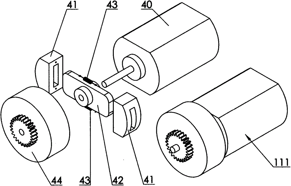
[0013] Specific implementation mode one: image 3 As shown, the thumb proximal knuckle force feedback detection driving device includes a driving part 111, and the driving part 111 includes a micro motor 40 and a clutch, and the clutch is pulled by a clutch friction plate 41, a friction plate slide bar 42, and a return The spring 43 and the clutch cover 44 are composed of the friction disc slide bar 42 and the shaft of the micro motor 40, and the two clutch friction plates 41 are inserted into the two ends of the friction disc slide bar 42 respectively. Position extension spring 43, clutch cover 44 is inserted into the axle of micromotor 40, is sliding contact between the axle of clutch cover 44 and micromotor 40, and clutch cover 44 is provided with transmission gear. Action implementation process: when the rotation speed of the micro motor 40 is higher than a certain value, the two clutch friction plates 41 overcome the pulling force of the return spring 43 and slide respect...

specific Embodiment approach 2

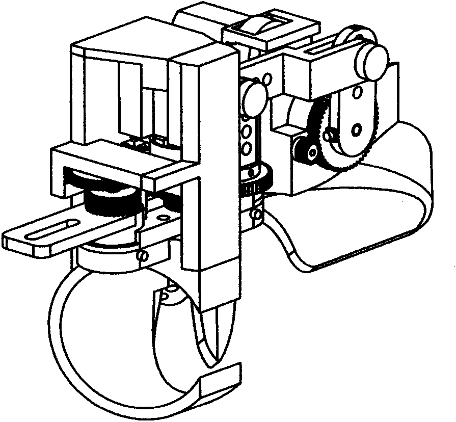
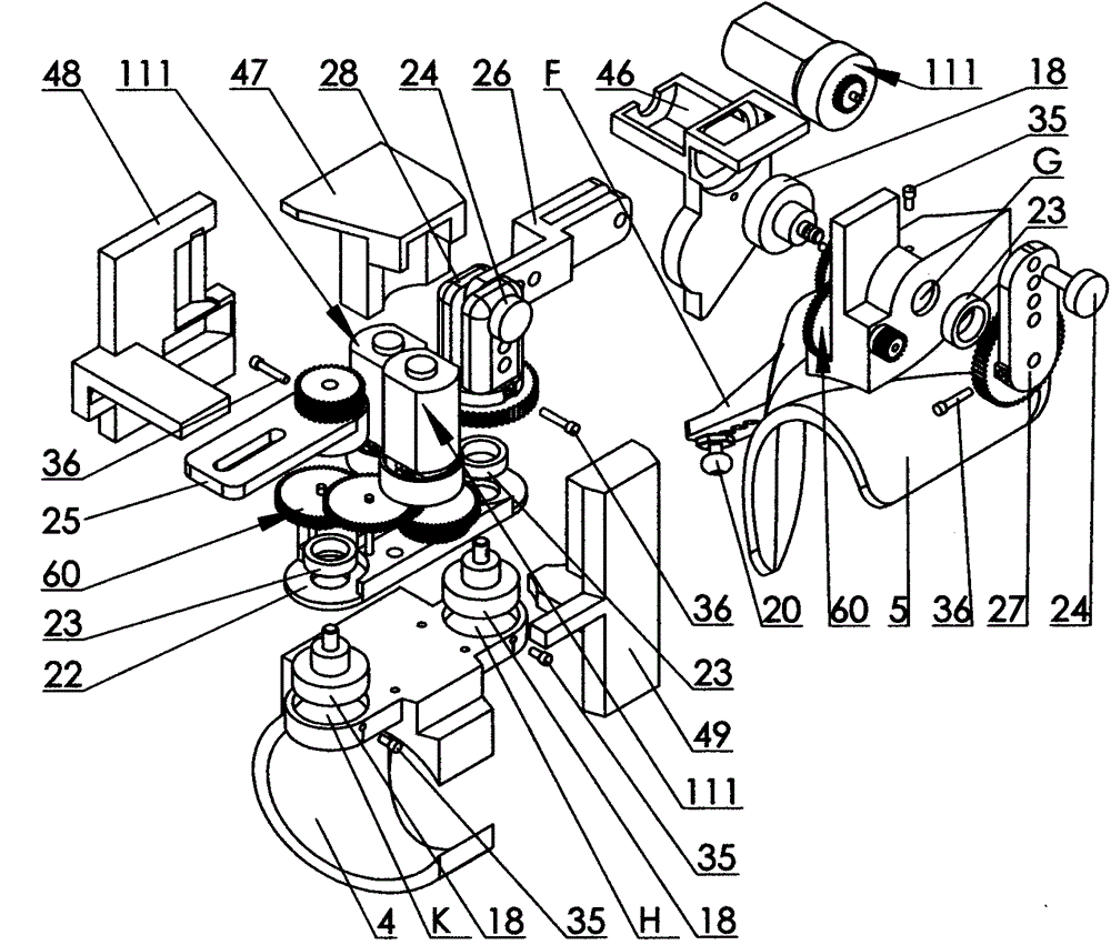
[0014] Specific implementation mode two: as figure 1 , figure 2 with image 3 As shown, the thumb proximal knuckle base 4 is fixed on the thumb proximal knuckle part of the human hand, the thumb proximal knuckle base 4 half surrounds the thumb proximal knuckle, and the cross section surrounding the junction is "C" shape, with an opening Facing the front side of the palm, there are two hole seats H and K at the position of the base on the outer side of the proximal knuckle of the thumb, and the positions of the two hole seats correspond to the metacarpophalangeal joint (MP) and interphalangeal joint of the thumb respectively (DIP). Thumb proximal knuckle base 4 and thumb metacarpophalangeal base 5 are hinged by rocking arm 28, connecting rod 26, rocking arm 27, and the bottom of said rocking arm 28 (embedded bearing 23) and the shaft of angle sensor 18 are passed through screw 36, the angle sensor 18 is fixed in the hole seat H of the thumb proximal knuckle base 4 by the ge...


PUM


Abstract

The invention relates to a device for detecting the human hand finger motion state and feeding back the force borne by the corresponding finger knuckle of a slave manipulator, in particular to a thumb near-knuckle force feedback detection driving device. The device aims at overcoming the defects that according to an existing force feedback device, a knuckle measuring mechanism and a force feedback mechanism are separated, the system is complex, the structure is complex, maintenance is difficult, bi-directional active driving cannot be achieved, and the cost is high. A knuckle detection mechanism and a force feedback mechanism are integrated, a unique connection way and a skillful knuckle measurement point layout are adopted, the finger to be detected can be kept flexible to the greatest degree when an operator uses the device, the motion state can be accurately detected, the controlled corresponding finger knuckle of the slave manipulator and the corresponding finger knuckle of the operator move coordinately and consistently, the stress condition of the slave manipulator in the specific working environment can be fed back to the operator, and therefore the virtual reality or remote operation immediacy sense is strengthened.

Description

technical field [0001] The invention relates to a data glove which detects the movement state of human fingers and has the function of two-way feedback force. Background technique [0002] Due to the development of science and technology, robots are gradually being used in an increasing range. As a reliable and mature robot, teleoperation robots are widely used in various dangerous, complex and inaccessible environments. It uses a very reliable control method, which is directly controlled by the operator's instructions. As the tasks performed by teleoperated robots become more and more complex, people put forward higher requirements for their flexibility while pursuing reliability, and it is necessary to implement teleoperation on complex manipulators to control the movement of multiple fingers of the manipulator. Multiple joints move together to achieve specific functions, which requires the use of data gloves, and the data glove with force feedback function is the most ef...

Claims


Application Information

Patent Timeline
IPC IPC(8): B25J13/00B25J13/08
Inventor 苏茂
Owner 苏茂
Why Eureka
Try Eureka