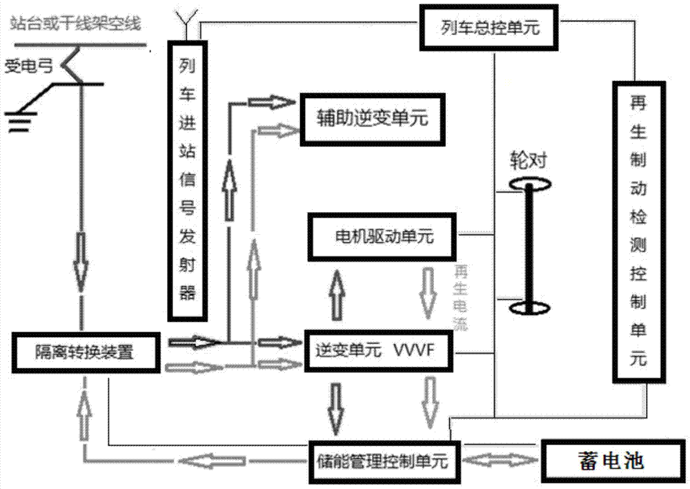
An on-board energy storage charging control device for electric vehicles

A charging control, electric vehicle technology, applied in battery circuit devices, electric vehicles, vehicle energy storage, etc., can solve the problems of high cost, exposed wires, low safety, etc., and achieve the effect of stable operation, convenient maintenance, and low cost

Inactive Publication Date: 2017-08-08
CHONGQING HENGTONG BUS
View PDF6 Cites 0 Cited by
  • Summary
  • Abstract
  • Description
  • Claims
  • Application Information

AI Technical Summary

Problems solved by technology

For the catenary power supply mode, when the vehicle is running, the pantograph is stretched out to contact the overhead cable for power supply. This power supply mode is technically mature and reliable, but due to the need to erect cable supports, it affects the urban landscape, and at the same time, the wires are exposed, so it is relatively safe. Low
The adopted third-rail power supply system is installed in contact with the collector shoe at the bottom of the vehicle and the third rail on the ground, which effectively solves the corresponding problems caused by the catenary power supply, but this type of system is complex and costly, and at the same time has great impact on the road. The conditions (drainage, cleaning, etc.) are demanding, and the requirements for municipal design and management are high
The on-board energy storage device can solve the problems caused by catenary and third rail power supply systems, but the use of on-board energy storage devices for full power supply has problems of large size and service life cycle

Method used


Image

  • An on-board energy storage charging control device for electric vehicles

Examples


Embodiment Construction

[0027] The embodiments of the present invention will be described in detail below. Examples of the embodiments are shown in the accompanying drawings, wherein the same or similar reference numerals indicate the same or similar elements or elements with the same or similar functions. The embodiments described below with reference to the drawings are exemplary, and are only used to explain the present invention, but should not be construed as limiting the present invention.

[0028] In the description of the present invention, it should be understood that the terms "longitudinal", "lateral", "upper", "lower", "front", "rear", "left", "right", "vertical", The orientation or positional relationship indicated by "horizontal", "top", "bottom", "inner", "outer", etc. is based on the orientation or positional relationship shown in the drawings, and is only for the convenience of describing the present invention and simplifying the description, not It indicates or implies that the pointed...


PUM


Abstract

The invention provides a vehicle-mounted energy-storing charging control device for an electric vehicle. A power supply input end of an isolation converting device is connected with an electric vehicle pantograph. A power supply output end of the isolation converting device is connected with the input end of an inversion unit. The output end of the inversion unit is connected with a motor driving unit which drives an electric vehicle wheel pair to move. The output end of the inversion unit is connected with the input end of an energy-saving management control unit. A signal output end of the energy-saving management control unit is connected with a signal input end of the isolation converting device. A signal interaction end of the energy-saving management control unit is connected with a signal interaction end of a storage battery. The energy-saving management control unit is used for power storing of an electric vehicle storage battery. A general control unit motor drives the signal output end to be connected with the motor driving unit. A general control unit inversion signal output end is connected with the inverting unit. The output end of the energy-saving management control unit of the general control unit is connected with the energy-saving management control unit. The advantages of a super capacitor are used, the shortcomings are effectively avoided, and power can be provided for a long time.

Description

Technical field [0001] The invention relates to the field of electronic circuits, in particular to a vehicle-mounted energy storage and charging control device for electric vehicles. Background technique [0002] Nowadays, trams mostly use overhead catenary, ground third rail contact power supply and on-board energy storage devices. For the catenary power supply method, when the vehicle is traveling, the pantograph is extended to contact the elevated cable for power supply. This power supply method is technically mature and reliable. However, due to the need to erect cable brackets, it affects the urban landscape, and the wires are exposed and safer low. The adopted third rail power supply system is powered by the contact between the collector shoe installed at the bottom of the vehicle and the third rail located on the ground, which effectively solves the corresponding problems caused by catenary power supply. However, this type of system is complex and costly, and it is not T...

Claims


Application Information

Patent Timeline
Patent Type & Authority Patents(China)
IPC IPC(8): B60L11/18B60L7/10H02J7/00
CPCY02T10/70Y02T10/72
Inventor 谢跃红王小磊苏世伟曾正森
Owner CHONGQING HENGTONG BUS
Why Eureka
Try Eureka