Hollow floor using steel mesh and thin plate combination for hole forming

A hollow floor, combined technology, applied in the direction of floor slabs, building components, buildings, etc., can solve the problems of increasing cost, inability of polystyrene blocks, and polystyrene blocks occupying loading space, etc.

Inactive Publication Date: 2015-05-20
王本淼 +2
View PDF7 Cites 23 Cited by
  • Summary
  • Abstract
  • Description
  • Claims
  • Application Information

AI Technical Summary

Problems solved by technology

[0007] The purpose of the present invention is to ensure the hole-forming specifications of the hollow floor, and then make full use of the hollow floor to realize the integration of building energy saving; organically combine the advantages of the steel mesh and the performance of the thin plate to become a cavity component for the hole-forming of the hollow floor, and the steel mesh becomes a hollow The top surface, bottom surface and two side walls of the cavity member; the thin plate can be made of waste recycling, which saves energy and reduces costs, and becomes the support body for the two sides of the two ends of the plugged cavity component and the inner wall of the steel mesh. Thin plates are placed in the grooves of the edge ribs to stabilize the structural strength of the steel mesh; the interaction between the steel mesh and the thin plates can improve the overall technical level of the cavity components, effectively solving the problem of vertical anti-floating, The surface of the cavity component needs to be isolated due to the horizontal displacement and the poor compatibility between the steel bar of the floor and the cavity component, and the defects of the bottom pad and the cavity component are easy to be damaged; in particular, the internal support of the cavity component and the sealing at both ends are solved When polyphenylene blocks are used as organic objects, the fire resistance level of special functional buildings is limited, and the density and bulk density of polyphenylene blocks need to be increased to increase the pressure capacity to support the construction load borne by the inner space of the steel mesh, and the polyphenylene blocks occupy the loading space during transportation. Defects such as increased cost, polyphenylene blocks must be made of standard expandable plastic particles, and waste cannot be recycled

Method used


Image

  • Hollow floor using steel mesh and thin plate combination for hole forming
  • Hollow floor using steel mesh and thin plate combination for hole forming
  • Hollow floor using steel mesh and thin plate combination for hole forming

Examples


Embodiment Construction

[0026] The invention will be further described below in conjunction with the accompanying drawings.

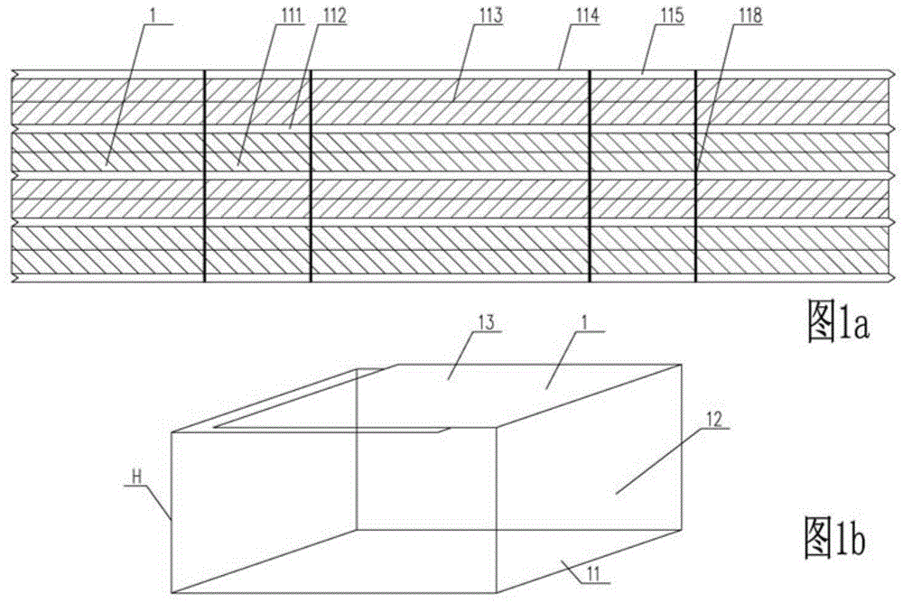
[0027] figure 1 Structural diagram of the cavity component steel mesh formed by the steel mesh and the thin plate in the first embodiment of the present invention, such as figure 1 As shown in a, the steel mesh of the cavity member 1 formed by the steel mesh and the thin plate contains a mesh plate 111, a reinforcing rib 112, a connecting plate 113 and an edge reinforcing rib 114, and the mesh plate and the reinforcing rib and the connecting plate and the edge reinforcing rib are The same thin steel plate is made by punching and stretching with a special machine; the steel mesh reinforcement rib is pressed in the vertical direction to have a bending mark 118 at the bending place that needs to be quantitatively bent during combination; figure 1 As shown in b, the length or height H of the bottom surface 11 of the hollow member, the side wall 12 of the hollow member and the top...


PUM


Abstract

A hollow floor using steel mesh and thin plate combination for hole forming comprises columns, beams, flange plates, and a cavity component formed by steel meshes and thin plates, wherein the beams are reinforced concrete beams or steel reinforced concrete combined beams; the flange plates are I-shaped section plates or T-shaped section plates; the cavity component is formed by the steel meshes and the thin plates which acts on each other; the steel meshes form the overall forming tetrahedron of the top plate, the bottom plate and two lateral walls of the hexahedron cavity component; the head and tail ends of the steel meshes overlap on one optional face of the tetrahedron; the thin plates include calcium silicate plates, plastic plates, composite plates, gypsum plates or corrugated plates; the thin plates form the other two lateral wall plates of the cavity component and the support plates between the top plate and the bottom plate of the cavity component; the two lateral wall plates formed by the thin plates are placed in edge reinforcing rib grooves at two edges of the steel meshes; in-situ concrete pouring is performed on the columns, the beams and the flange plates.

Description

technical field [0001] The invention relates to a hollow floor which uses a cavity member to form a hole without centering, in particular to a hollow floor which uses a steel mesh and a thin plate to form a hole. Background technique [0002] At present, in the technical field of cast-in-place reinforced concrete hollow floors, fully sealed or lightweight solid cavity components are usually used to form holes and form hollow floors, such as ZL200410082381.9 "a hollow small ribbed building" declared by the inventor "cover", using fully sealed thin-walled box cavity components buried in the small ribbed floor to form a "T-shaped" force section hollow layer, which solves the problem of "T-shaped" force section small dense rib hollow floor Problem with slippery roof. However, there is no designed stress reinforcement between the bottom of the fully-sealed thin-walled box cavity member and the hollow floor formwork, and a layer of crack-resistant steel wire mesh must be applied ...

Claims


Application Information

Patent Timeline
Patent Type & Authority Applications(China)
IPC IPC(8): E04B5/36
Inventor 王本淼王海崴
Owner 王本淼
Why Eureka
Try Eureka