Minitype foil aerodynamic pressure bearing

A gas dynamic pressure bearing and foil technology, applied in the direction of sliding contact bearings, rotating bearings, bearings, etc., can solve problems such as difficult to assemble bearing performance, difficult to process wave foils, and difficulties, so as to improve the carrying capacity and make it easy to take off , the effect of large carrying capacity

Inactive Publication Date: 2015-05-20
HUNAN UNIV
View PDF7 Cites 28 Cited by
  • Summary
  • Abstract
  • Description
  • Claims
  • Application Information

AI Technical Summary

Problems solved by technology

[0006] The purpose of the present invention is to at least partly solve the above-mentioned technical problems, and provide a micro-foil aerodynamic pressure bearing to solve the problems such as diffic

Method used


Image

  • Minitype foil aerodynamic pressure bearing
  • Minitype foil aerodynamic pressure bearing
  • Minitype foil aerodynamic pressure bearing

Examples


Embodiment 1

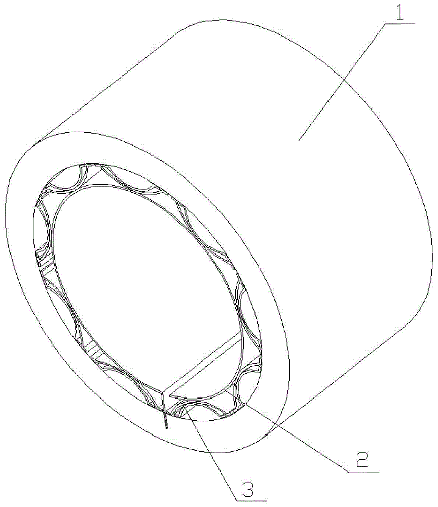
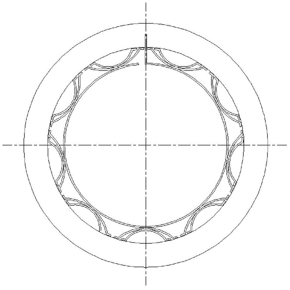
[0026] Such as figure 1 As shown, a miniature foil gas dynamic pressure bearing, the gas bearing includes a bearing body 1 , a top foil 2 and a composite elastic wave foil structure 3 . The bearing body 1 is the main structure of the bearing, which plays the role of installation, protection and support; the top layer foil 2 is the inner surface of the bearing, so that the bearing has a continuous air pressure distribution; the composite elastic wave foil structure 3 provides a certain damping and stiffness. Such as figure 2 As shown, the composite elastic wave foil structures 3 are evenly distributed between the bearing body 1 and the top foil 2, and there are N pieces in total.

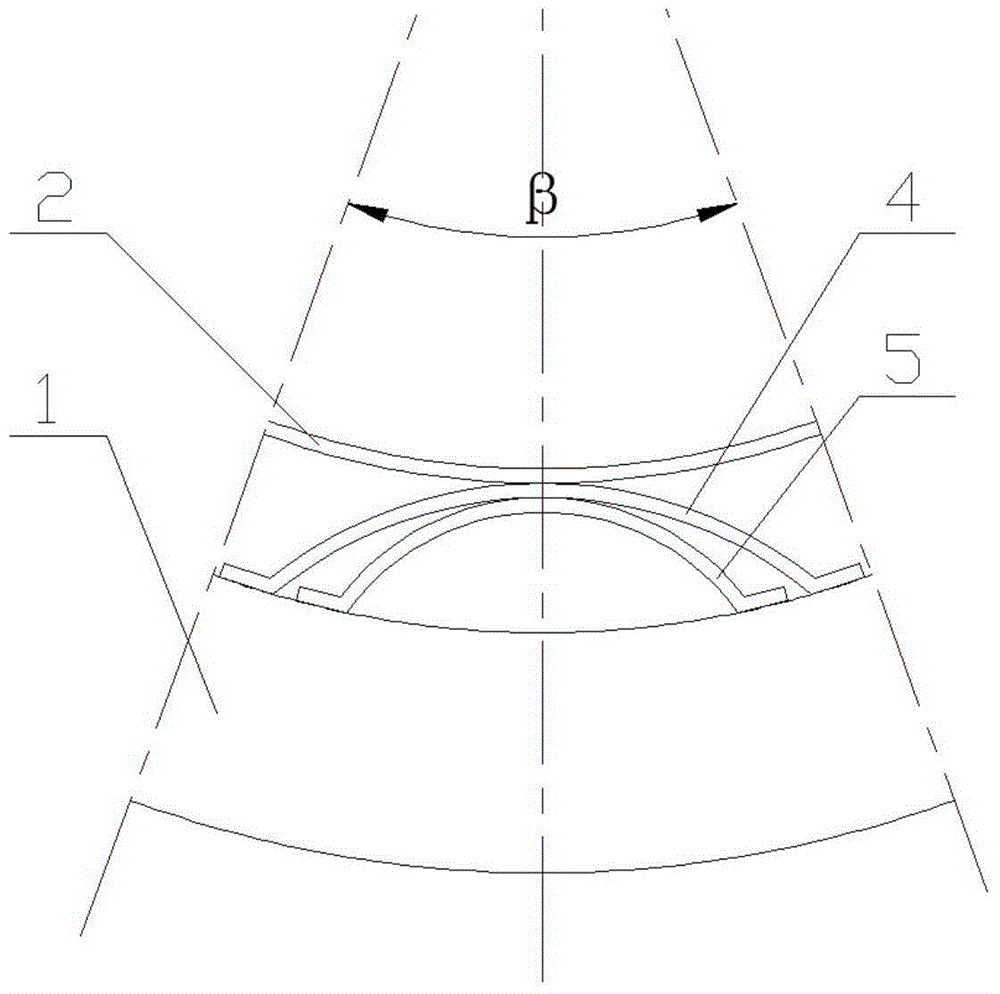
[0027] Such as image 3 As shown, the composite elastic wave foil structure 3 is composed of an outer elastic wave foil 4 and an inner elastic wave foil 5, which are manufactured as a whole using LIGA processing technology, and there are 2N pieces in total; each composite elastic wave foil struct...

Embodiment 2

[0030] Image 6 Shown is a schematic structural view of another micro-foil aerodynamic pressure bearing provided in the second embodiment of the present invention.

[0031] The working principle of the bearing in this embodiment is generally the same as that in Case 1, except that the corrugated foil structure in this embodiment is a multi-legged structure. The composite elastic wave foil structure 3 in the first embodiment requires high dimensional accuracy, and the installation is not very convenient, and the structure is relatively complicated. The difference from Example 1 is that the multi-legged structure in Example 2 retains the advantages of the composite elastic wave foil structure 3, but does not require too high dimensional accuracy, and the processing difficulty is relatively low, so it is more convenient to manufacture, and at the same time The installation is not troublesome, and the damping characteristics are better, which further improves the impact vibration...


PUM


Abstract

The invention discloses a minitype foil aerodynamic pressure bearing. The minitype foil aerodynamic pressure bearing comprises a bearing body, a top layer foil and a composite elastic wave foil structure, wherein the composite elastic wave foil structure is connected with the top layer foil for circumferential location, the composite elastic wave foil structure comprises an outer elastic wave foil and an inner elastic wave foil, the convex surface of the inner side of the composite elastic wave foil structure is connected with the tangent position of the outer surface of the top layer foil, the convex surface of the outer side of the composite elastic wave foil structure is contacted with the inner surface of the bearing body, and the bearing body has mounting, protecting and supporting actions; and a matching surface of the bearing and a rotating shaft is formed on the inner surface of the top layer foil. According to the minitype foil aerodynamic pressure bearing, the surface quality and the performance parameters of the wave foil are improved, the bearing damping and stiffness characteristics are improved, the bearing capacity and the impact vibration cushioning capability of the bearing are improved remarkably, and the life and the stability of the bearing are prolonged and improved.

Description

technical field [0001] The invention relates to the technical field of air bearings, in particular to a miniature foil gas dynamic pressure bearing. Background technique [0002] As an important branch of micro-electro-mechanical system (MEMS), micro-rotating machinery can not only provide energy for MEMS, but also is a very important actuator, such as micro gas turbines for remote robots, micro air for micro fuel cells, etc. Presses, children's artificial hearts, propellers for micro-drones, power generation systems for micro-robots and micro-satellites, etc. In recent years, with the development of 3D printing, laser processing, Mold SDM and other technologies, it has provided important technical support and development opportunities for the development of micro-rotating machinery. However, as the basic core component in the electromechanical system, the bearing has always lagged behind the development of other technologies, and has become a key technology that limits the...

Claims


Application Information

Patent Timeline
IPC IPC(8): F16C17/02
Inventor 冯凯刘远远程苗苗
Owner HUNAN UNIV
Why Eureka
Try Eureka