Special tool for lifting tubular bus bar
A technology of tubular busbars and special tools, applied in busbar installation, cable installation, transportation and packaging, etc., can solve the problems of low work efficiency, high work intensity, high safety risks, etc., and achieve simple structure and reduce work. Strength, safety risk reduction effect
- Summary
- Abstract
- Description
- Claims
- Application Information
AI Technical Summary
Problems solved by technology
Method used
Image

Examples
specific Embodiment approach 1
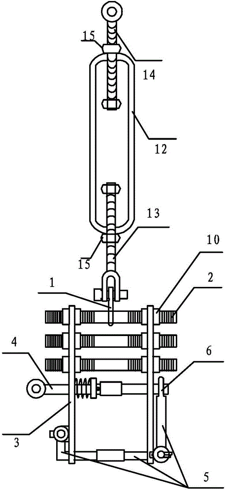
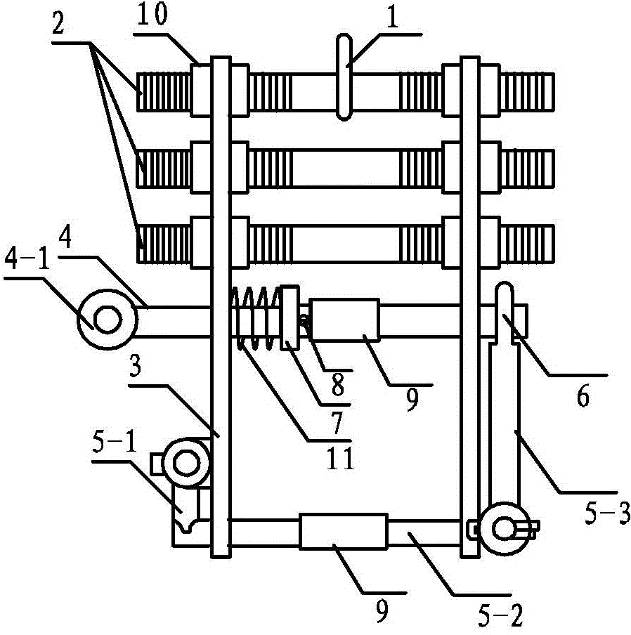
[0029] Specific implementation mode 1, refer to Figure 1 to Figure 8 Specifically explain this embodiment, the special tool for hoisting tubular busbar described in this embodiment, it includes two-way adjuster, special spreader, rubber sheath 9 and nut 15; 13 and reverse buckle adjusting bolt 14; the special spreader includes suspension ring 1, n adjusting screw rods 2, support frame 3, tripping shaft 4, tripping device 5, tripping device fixing ring 6 and adjusting screw fixing nut 10; 10 ≥n≥3;
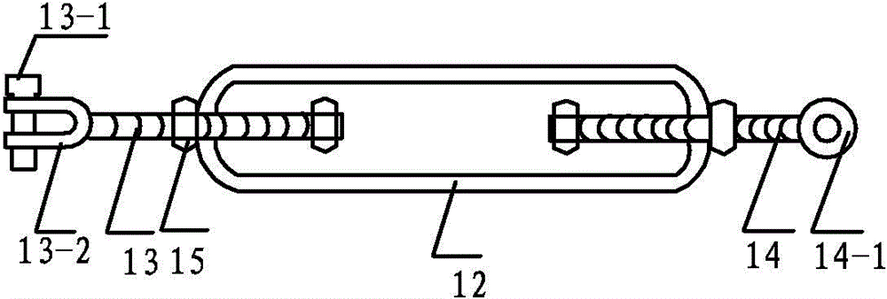
[0030] The two-way adjusting bracket 12 is an elliptical steel ring, and the long semi-axis of the oval steel ring is 4 to 5 times the short semi-axis; both the forward buckle adjusting bolt 13 and the reverse buckle adjusting bolt 14 are threadedly connected with the two-way adjusting bracket 12 , and the positive buckle adjusting bolt 13 and the reverse buckle adjusting bolt 14 are all located on the central axis of the two-way adjusting bracket 12; one end of the positive buckl...
specific Embodiment approach 2
[0046] Embodiment 2. This embodiment is a further description of the special tool for hoisting tubular busbars described in Embodiment 2. In this embodiment, the connecting buckle includes a U-shaped arc 13-2 and a latch 13-1; The pin 13-1 passes through the two parallel faces of the U-shaped arc 13-2.
specific Embodiment approach 3
[0047] Specific embodiment three. This specific embodiment is a further description of the special tool for hoisting tubular busbars described in specific embodiment one. In this embodiment, it also includes a trip shaft limiter 7 and a trip shaft limit pin. Pin 8 and limit spring 11, the trip shaft limiter 7 is located on the trip shaft 4 between two rectangular steel plates to prevent the trip shaft 4 from falling off; the trip shaft limit pin 8 is used to fix the The position of the trip shaft limiter 7 is described; the limit spring 11 is sleeved on the trip shaft 4, and is located between the trip shaft limiter 7 and the rectangular steel plate close to the trip ring 4-1.
[0048] In this embodiment, the tripping shaft 4 is restricted by the tripping shaft limiter 7 and will not come out, preventing the tripping shaft 4 from falling off and damaging equipment and personnel, and the special lifting tool is separated from the pipe busbar to realize free tripping.
PUM
| Property | Measurement | Unit |
|---|---|---|
| Thread length | aaaaa | aaaaa |
| Thickness | aaaaa | aaaaa |
| Length | aaaaa | aaaaa |
Abstract
Description
Claims
Application Information
 - R&D
- Intellectual Property
- Life Sciences
- Materials
- Tech Scout
- Unparalleled Data Quality
- Higher Quality Content
- 60% Fewer Hallucinations
Browse by: Latest US Patents, China's latest patents, Technical Efficacy Thesaurus, Application Domain, Technology Topic, Popular Technical Reports.
© 2025 PatSnap. All rights reserved.Legal|Privacy policy|Modern Slavery Act Transparency Statement|Sitemap|About US| Contact US: help@patsnap.com