Motor
A motor and salient pole technology, applied in the field of motors, can solve the problems of the contact between the magnet and the bobbin, the change of the installation position, the protrusion of the radial inner position, etc., to achieve the effect of improving the assembly efficiency
- Summary
- Abstract
- Description
- Claims
- Application Information
AI Technical Summary
Problems solved by technology
Method used
Image
Examples
Embodiment approach 1
[0068] - Embodiment 1 -
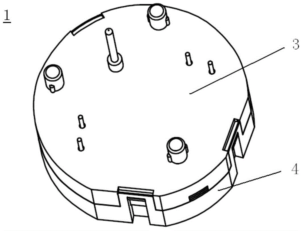
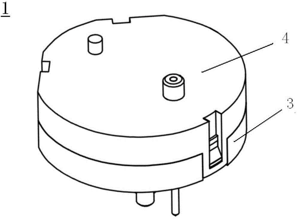
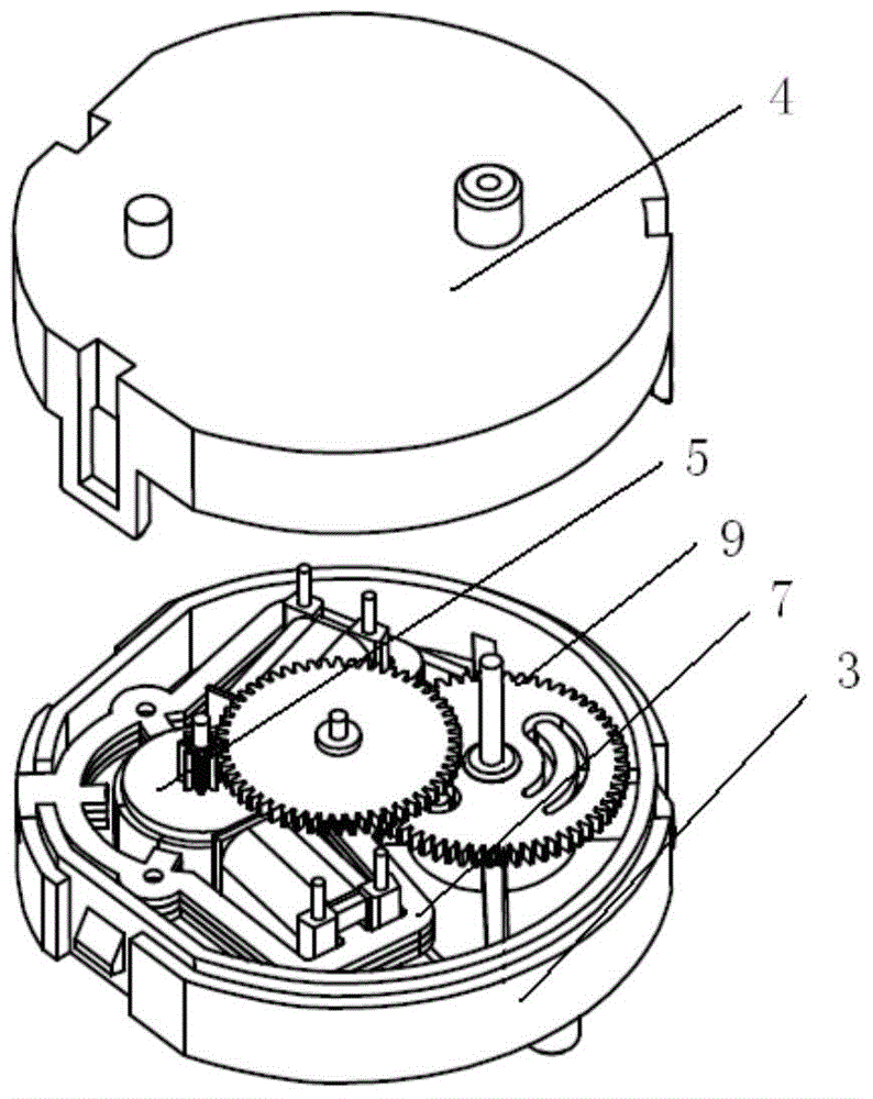
[0069] according to Figure 1 to Figure 10 , to describe Embodiment 1 of the present invention, wherein, figure 1 It is an external perspective view of the motor according to Embodiment 1 of the present invention viewed from one direction (the output shaft side of the motor), figure 2 is an external perspective view of the motor according to Embodiment 1 of the present invention viewed from another direction (the side opposite to the output shaft of the motor), image 3 is a perspective view of the motor according to Embodiment 1 of the present invention with the second casing constituting a part of the casing separated and shown, Figure 4 It is an exploded perspective view of the motor according to Embodiment 1 of the present invention, Figure 5 is an explanatory plan view of the motor according to Embodiment 1 of the present invention, Figure 6 is an explanatory side view of the motor according to Embodiment 1 of the present invention, Fi...
Embodiment approach 2
[0088] - Embodiment 2 -
[0089] The motor according to Embodiment 2 of the present invention is basically the same in structure as the motor according to Embodiment 1 above. The only difference lies in the structure of the stator core. Figure 11 , Figure 12 To illustrate, among them, Figure 11 is a plan view of a stator core of a motor according to Embodiment 2 of the present invention, Figure 12 It is a perspective view of the stator of the motor in Embodiment 2 of this invention.
[0090] In this embodiment, if Figure 11 As shown, first protrusions 851 and 851 protruding inward are symmetrically formed on the inner peripheral edge of the connecting portion of the stator core with the first salient pole 81 interposed therebetween, and inside the connecting portion of the stator core First protrusions 851 , 851 protruding inward are symmetrically formed on the periphery so as to sandwich the second salient pole 82 . ,like Figure 12 As shown, the flange portions of...
Embodiment approach 3
[0093] - Embodiment 3 -
[0094] The motor according to Embodiment 3 of the present invention is basically the same in structure as the motors of Embodiment 1 and Embodiment 2 above. The only difference lies in the structure of the stator core and the bobbin. Therefore, the following will focus on the differences, according to Figure 13 to Figure 18 To illustrate, among them, Figure 13 is a plan view of a stator core of a motor according to Embodiment 3 of the present invention, Figure 14 is a perspective view of a stator core of a motor according to Embodiment 3 of the present invention, Figure 15 It is a perspective view of the bobbin of the motor according to Embodiment 3 of the present invention viewed from one direction, Figure 16 It is a perspective view of the bobbin of the motor according to Embodiment 3 of the present invention viewed from another direction, Figure 17 In the motor according to Embodiment 3 of the present invention, in the state where the bob...
PUM
 Abstract
Description
Claims
Application Information
 - R&D
- Intellectual Property
- Life Sciences
- Materials
- Tech Scout
- Unparalleled Data Quality
- Higher Quality Content
- 60% Fewer Hallucinations
Browse by: Latest US Patents, China's latest patents, Technical Efficacy Thesaurus, Application Domain, Technology Topic, Popular Technical Reports.
© 2025 PatSnap. All rights reserved.Legal|Privacy policy|Modern Slavery Act Transparency Statement|Sitemap|About US| Contact US: help@patsnap.com


