Medical venous transfusion monitor

A technology for intravenous infusion and monitors, which is applied in flow monitors, other medical equipment, pharmaceutical equipment, etc. It can solve problems such as false alarms, large detection errors, and missed alarms, so as to avoid false detection and missed detection, and ensure accurate detection. Sex, the effect of avoiding false detection

Inactive Publication Date: 2015-05-27
李洪升
View PDF10 Cites 17 Cited by
  • Summary
  • Abstract
  • Description
  • Claims
  • Application Information

AI Technical Summary

Problems solved by technology

[0003] At present, commonly used infusion monitors are based on infrared tube voltage monitoring technology, such as the utility model patent document with the patent publication number CN201572367 and the invention name "Infrared Infusion Alarm", and the patent publication number CN202777298 and the invention name is The utility model patent documents of "an infusion alarm" all disclose an infusion alarm that uses the infrared tube voltage monitoring technology. Whether the flow is finished, neither the infusion drip speed nor the change of the infusion drip speed can be detected
Moreover, due to the different penetration properties of infrared rays to different infusion tubes (such as brown or transparent) and different intravenous infusions (colorless and clear, colored and clear, translucent, opaque), that is to say, the normal infusion process The reference sampling voltage is different, and the sampling voltage when the liquid is empty and the tube is empty is also different. Therefore, triggering the alarm by sampling the voltage in different situations often results in false alarms or miss

Method used


Image

  • Medical venous transfusion monitor
  • Medical venous transfusion monitor
  • Medical venous transfusion monitor

Examples


Embodiment Construction

[0042] The present invention will be further described below in conjunction with the accompanying drawings and embodiments.

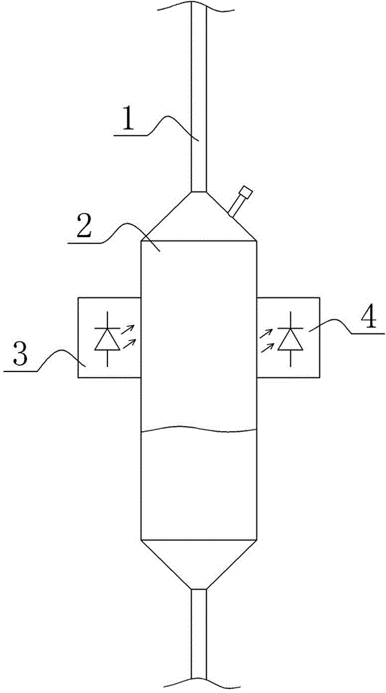
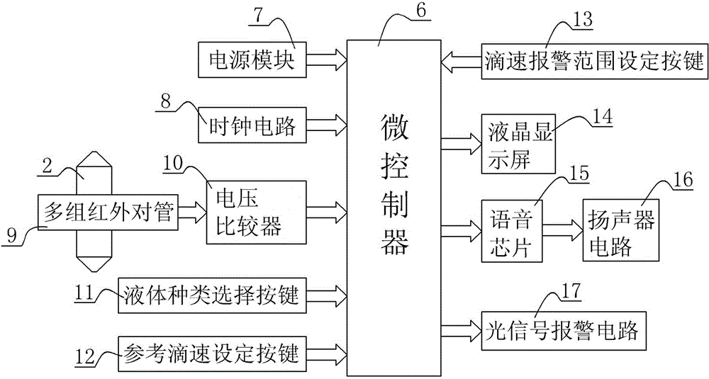
[0043] The medical intravenous transfusion monitor of the present invention is composed of a detection circuit and a control circuit. The detection circuit detects whether there is medicine dripping in the drip pot, and inputs the detection signal into the control circuit. The control circuit calculates the dripping speed of the medicine according to the detected signal, and can judge whether the medicine is empty and whether the current dripping speed exceeds the range; when the medicine is empty or the dripping speed exceeds the range, it can send out an audible and visual alarm signal to realize the medical care. Personnel reminder.

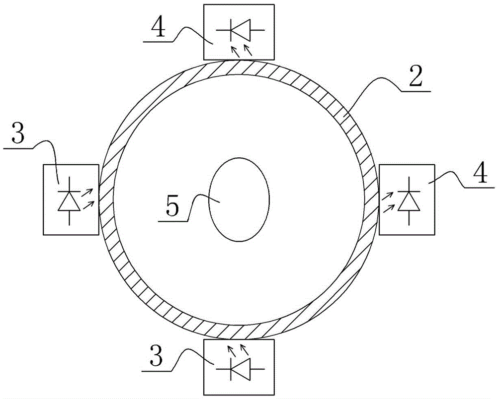
[0044] The detection circuit is composed of multiple groups of infrared pair tubes, and each group of infrared pair tubes is composed of an infrared emitting tube 3 and an infrared receiving tube 4, and the infrared emi...


PUM


Abstract

The invention discloses a medical venous transfusion monitor. The medical venous transfusion monitor comprises a detecting circuit and a control circuit, wherein the detecting circuit consists of infrared pair transistors and a voltage comparator. The medical venous transfusion monitor is characterized in that two or more than two groups of infrared pair transistors are arranged, wherein each group of infrared pair transistors is arranged on the same height position of a drip cup; the threshold value voltage is one half the sum of output voltage when the infrared pair transistors mounted on the drip cup are shielded by medical drops and output voltage when the infrared pair transistors mounted on the drip cup are unshielded by the medical drops. A monitoring method comprises the following steps: a), connecting equipment; b), selecting liquid types; c), setting a dripping speed alarm range; d), setting reference dripping speed; e), obtaining existing dripping speed; f) performing dripping speed ultra-limit judgment; g), judging drug flow-empty. According to the monitor and the monitoring method disclosed by the invention, false detection and leakage detection of a conventional transfusion alarm are avoided, whether the current dripping speed and the liquid medicine are emptied or not can be judged, the beneficial effects are remarkable, and the application and the popularization are convenient.

Description

technical field [0001] The present invention relates to a medical intravenous infusion monitor, more specifically, to a medical intravenous infusion monitor which realizes drug drip speed detection through multiple sets of infrared paired tubes and can alarm when the drug liquid is empty and the drip speed exceeds the range. . Background technique [0002] Intravenous infusion is an operation item widely used in modern medical activities. Usually, when the patient is infused, the patient or the accompanying person is required to assist the nursing staff to continuously observe the progress of the infusion. Because the infusion time is often long, it is inevitable for the patient or the accompanying staff to be negligent, and cannot find in time that the liquid in the infusion bottle has been emptied, causing the patient's venous blood to return, causing unnecessary loss and pain, and even threatening the patient's life. Different types or concentrations of intravenous infu...

Claims


Application Information

Patent Timeline
IPC IPC(8): A61M5/172
CPCA61M5/1685A61M5/16804A61M5/16886A61M2205/18A61M2205/3334A61M2205/3341
Inventor 李洪升
Owner 李洪升
Why Eureka
Try Eureka