Clamping device for cylindrical work-piece line cutting machining

A clamping device and wire cutting technology, applied in the field of mechanical processing, can solve the problems of accuracy requirements affecting dimensional accuracy and shape tolerance, easy deformation, poor rigidity, etc., and achieve low processing accuracy requirements, low production costs, The effect of long service life

Inactive Publication Date: 2015-05-27
XIAN ZHONGZHI HUIZE PHOTOELECTRIC TECH
View PDF0 Cites 9 Cited by
  • Summary
  • Abstract
  • Description
  • Claims
  • Application Information

AI Technical Summary

Problems solved by technology

When using a wire cutting machine tool to process a thin-walled cylinder, it is necessary to use a clamping device to tighten the thin-walled cylinder. At that time, because the thin-walled cylinder has the characteristics of thin wall, poor rigidity and weak strength, it is easy to deform during the clamping process. Thus affecting the accuracy requirements of its dimensional accuracy and shape and position tolerance

Method used


Image

  • Clamping device for cylindrical work-piece line cutting machining
  • Clamping device for cylindrical work-piece line cutting machining

Examples


Embodiment Construction

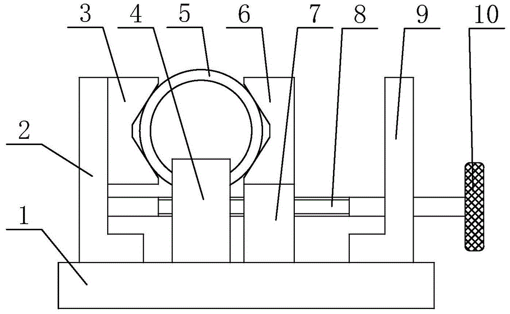
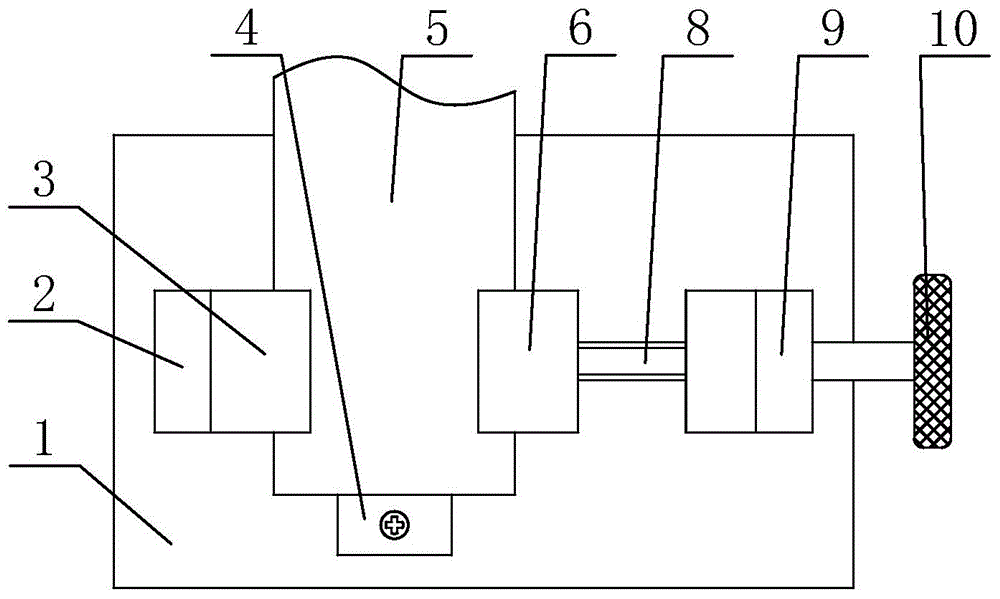
[0019] like figure 1 and figure 2 The shown clamping device for wire cutting processing of a cylindrical workpiece includes a rectangular base 1, a symmetrically arranged L-shaped bracket 1 2 and an L-shaped bracket 2 9, and also includes a positioning device for positioning the end of the workpiece 5 to be processed. Plate 4, the V-shaped cushion block 3 and the V-shaped pressing head 6 for clamping the workpiece 5, the sliding support 7 for supporting the V-shaped pressing head 6 and the sliding support 7 for driving the The upper side of the rectangular base 1 is a screw 8 that moves back and forth; one end of the upper side of the rectangular base 1 is fixedly provided with the L-shaped support 2, and the other end of the upper side of the rectangular base 1 is fixedly provided with the L-shaped support 2 9. A V-shaped spacer 3 is fixedly installed on the L-shaped support 2, and the upper side of the rectangular base 1 is located between the L-shaped support 2 and the L-...


PUM


Abstract

The invention discloses a clamping device for cylindrical work-piece line cutting machining. The device comprises a rectangular base, a first L-shaped support and a second L-shaped support. The first L-shaped support and the second L-shaped support are fixed at the two ends of the upper side of the rectangular base respectively. A V-shaped cushioning block is fixed on the first L-shaped support, a sliding support is in arranged on the upper side of the rectangular base, a V-shaped compression head is fixed at the upper end of the sliding support, a location plate is fixed on the upper side of the rectangular base, one end of a screw penetrates an unthreaded hole of the second L-shaped support and a threaded hole of the sliding support to be hinged to the first L-shaped support, and a drive handle is arranged at the other end of the screw. The clamping device has the advantages of being reasonable in design, simple in structure, high in machining accuracy, capable of facilitating work-piece dismounting, low in labor intensity, high in production efficiency, long in service life, low in production cost and convenient to promote and use.

Description

technical field [0001] The invention belongs to the technical field of mechanical processing, and relates to a fixture device, in particular to a clamping device for processing a columnar workpiece by a wire cutting machine tool. Background technique [0002] The wire-cut electric discharge machine was invented in the Soviet Union in 1960. Because the wire-cut processing is suitable for the processing of high hardness, difficult-to-machine materials and complex cavities, it plays a very important role in the manufacturing industry, especially in mold processing. When using a wire cutting machine tool to process a thin-walled cylinder, it is necessary to use a clamping device to tighten the thin-walled cylinder. At that time, because the thin-walled cylinder has the characteristics of thin wall, poor rigidity and weak strength, it is easy to deform during the clamping process. As a result, the accuracy requirements of its dimensional accuracy and shape and position tolerance ...

Claims


Application Information

Patent Timeline
Patent Type & Authority Applications(China)
IPC IPC(8): B23Q3/06B23H7/02
CPCB23H11/003B23H7/02
Inventor 侯鹏
Owner XIAN ZHONGZHI HUIZE PHOTOELECTRIC TECH
Why Eureka
Try Eureka