Reforming reactor fan-shaped barrels capable of reducing catalyst leakage

The technology of reforming reactor and fan-shaped cylinder is applied in the direction of catalytic reforming of naphtha, which can solve the problems of long-term operation hidden danger, damage and different expansion of the device, so as to eliminate catalyst leakage, reduce production cost, The effect of reducing wear

Active Publication Date: 2015-05-27
PETROCHINA CO LTD
View PDF5 Cites 1 Cited by
  • Summary
  • Abstract
  • Description
  • Claims
  • Application Information

AI Technical Summary

Problems solved by technology

[0003] Since the internal parts of the reforming reactor are very complicated and there are a lot of connecting parts, during the high-temperature thermal expansion process, the expansion amount is different, which leads to deformation, cracking, damage and other problems of the internal components such as the reactor fan-shaped cylinder and the conical cover plate.
Moreover, the reforming reactor is greatly affected by fluctuations in raw materials, temperature, and pressure. Damage to the fan-shaped cylinder will lead to catalyst leakage, which will increase catalyst consumption. Catalyst leakage will reduce the octane number of the product, reduce the content of aromatics, and reduce the purity of hydrogen. The product quality and the safe and stable operation of downstream devices have caused great hidden dangers to the long-term operation of the devices

Method used


Image

  • Reforming reactor fan-shaped barrels capable of reducing catalyst leakage
  • Reforming reactor fan-shaped barrels capable of reducing catalyst leakage
  • Reforming reactor fan-shaped barrels capable of reducing catalyst leakage

Examples


Embodiment Construction

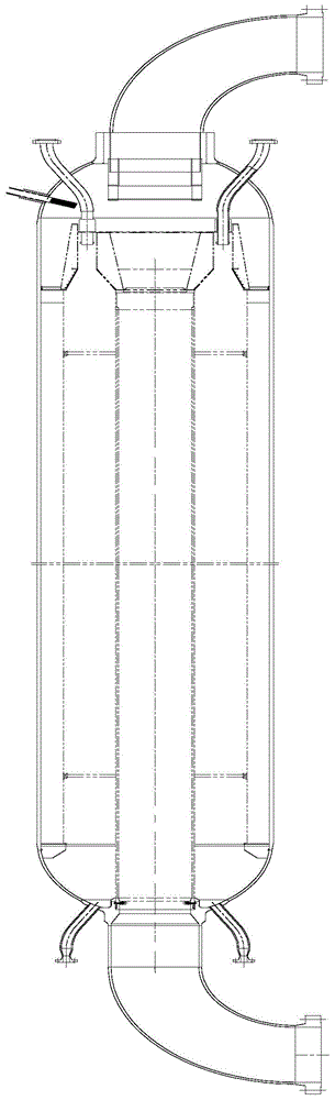
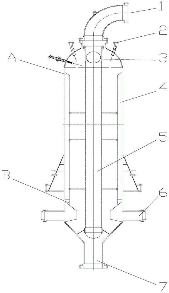
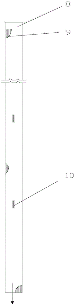
[0019] use image 3 , Figure 4 The fan-shaped cylinder of the reforming reactor shown is a Johnson mesh fan-shaped cylinder, and is used figure 2 The structure is installed in the reforming reactor. The upper part of the fan-shaped tube 4 of the reforming reactor is at the top of the reactor, and is basically flush with the weld seam line of the reactor head. The top of the fan-shaped tube is sealed, and the top smooth pipe is wedge-shaped. The angle between the wedge-shaped slope and the back of the fan-shaped tube is 45 degrees. The fan-shaped cylinder is evenly distributed along the inner wall of the reactor, and 3 to 5 sets of support frames 10 are used to make it close to the inner wall of the reactor, which reduces the wear of the catalyst on the fan-shaped cylinder; the opening at the bottom of the fan-shaped cylinder is connected with the manifold 11 at the bottom of the reactor, The way of connection is that there is an annular groove at the bottom of the fan-shap...


PUM


Abstract

The invention relates to reforming reactor fan-shaped barrels. The reforming reactor fan-shaped barrels are Johnson screen fan-shaped barrels; the cross sections of the reforming reactor fan-shaped barrels shape like fans; when the reforming reactor fan-shaped barrels are used, the back parts of the reforming reactor fan-shaped barrels are firmly pressed against the inner wall of a reactor; the top parts of the reforming reactor fan-shaped barrels are sealed; the bottoms of the reforming reactor fan-shaped barrels are provided with openings and are connected with a collecting tube arranged on the bottom of the reactor; oil gas discharged out of the reforming reactor fan-shaped barrels is mixed in the collecting tube, and is discharged via an oil gas outlet. No connection part of the reforming reactor fan-shaped barrels is observed, almost no leakage point is generated, so that catalyst leakage is avoided; no connection part is observed between a central tube and the reforming reactor fan-shaped barrels, so that deformation and damage of the reforming reactor fan-shaped barrels caused by nonuniform thermal expansion are avoided; the reforming reactor fan-shaped barrels are capable of reducing production cost, and ensuring safe stable long-period operation of equipment.

Description

technical field [0001] The invention relates to a fan-shaped cylinder structure for reducing catalyst leakage, in particular to a fan-shaped cylinder structure for a reforming reactor of a continuous catalytic reforming device for petroleum processing. Background technique [0002] Catalytic reforming unit is an important process in the secondary processing of petroleum. It is a catalyst for the purpose of producing high-octane gasoline components and aromatics from low-octane straight-run naphtha under the action of a catalyst through a series of special reactions. reaction process. The reforming reactor is an important equipment of the reforming unit and also the core part of the whole reforming unit. The role of the reforming reactor is to allow the hydrocarbons to contact the catalyst under reaction conditions without allowing the catalyst to leave without entraining the product. The equipment is a radial reactor, which operates in a high-temperature hydrogen-facing en...

Claims


Application Information

Patent Timeline
IPC IPC(8): C10G35/04
CPCC10G35/04
Inventor 魏治中俄克斌许岩丁立海王正元王志奉刘文陈兴虎兰创宏王桂华何灵生慕希豹张小芳李虎全鱼自忠
Owner PETROCHINA CO LTD
Why Eureka
Try Eureka