Synchronous coordinated control method of series-parallel automobile electrophoretic painting conveying mechanism

A conveying mechanism and electrophoretic coating technology, applied in electrolytic coating, electrophoretic plating, coating, etc., can solve problems such as difficult to obtain accurate dynamic parameters, difficult to control effects, and irreversible synchronization errors of connecting rods

Inactive Publication Date: 2015-05-27
JIANGSU UNIV
View PDF6 Cites 5 Cited by
  • Summary
  • Abstract
  • Description
  • Claims
  • Application Information

AI Technical Summary

Problems solved by technology

[0005] However, the above-mentioned related control technologies all combine the cross-coupling control technology with the traditional PD control technology. They all require accurate model information of the system and all states can be measured. For a multi-input multi-output system with coupling, nonlinear dynamics, and parameter uncertain characteristics, it is difficult to obtain its dynamic parameters accurately, such as the position of the center of mass and the moment of inertia that changes with the movement of the mechanism. If the above technology is used, it will be difficult to obtain better In addition, the synchronization errors proposed by the above-mentioned related control technologies are all based on the definition of conventional synchronization errors. If the car body fixing frame and the car body are placed on the pole, if the traditional conventional synchronization error setting method is adopted, only the synchronization error between the active joints in the mechanisms on both sides will be considered, and the synchronization error at both ends of the connecting rod will not be eliminated.
Therefore, the above method is not suitable for the hybrid automobile electrophoretic coating conveying mechanism involved in the present invention, or it is difficult to obtain a better control effect after being applied to the conveying mechanism

Method used


Image

  • Synchronous coordinated control method of series-parallel automobile electrophoretic painting conveying mechanism
  • Synchronous coordinated control method of series-parallel automobile electrophoretic painting conveying mechanism
  • Synchronous coordinated control method of series-parallel automobile electrophoretic painting conveying mechanism

Examples


Embodiment

[0111] The Fangming control method mainly focuses on solving the synchronous coordination control problem of the hybrid automobile electrophoretic coating conveying mechanism with a synchronous coordination control technology, and realizes high-performance control of the mechanism. The specific implementation of this control method is as follows:

[0112] 1. Solve the Jacobian matrix

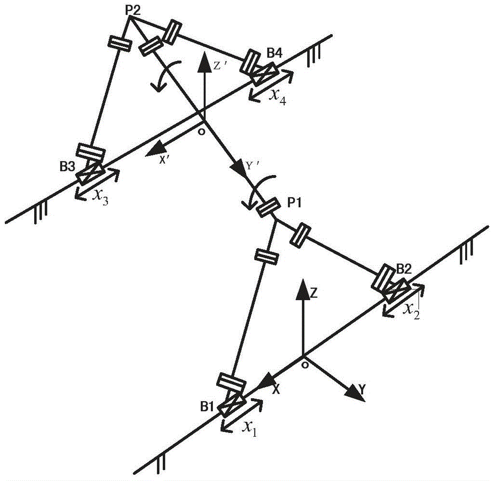
[0113] exist figure 2 In this method, the rod length constraint equation is used, and the kinematics inverse solution equation of the mechanism can be obtained according to the structure of the lifting and turning mechanism:

[0114] x 1 2 + z 1 2 = L 1 2 ...


PUM


Abstract

The invention discloses a synchronous coordinated control method of a series-parallel automobile electrophoretic painting conveying mechanism. The method comprises the following steps: taking the series-parallel automobile electrophoretic painting conveying mechanism as a controlled object, building a kinetic model of the conveying mechanism in a cartesian space, adopting a distributed structure to build a synchronous coordinated control hardware system of the conveying mechanism according to a control requirement of the conveying mechanism, and providing a novel synchronous error according to the structure characteristic and movement characteristic of the lifting turnover mechanism of the conveying mechanism, combining the novel synchronous error with a sliding-mode control, further designing a kinetic synchronous coordinated control rule based on the sliding-mode control, and finally performing software programming through VC++ to realize the synchronous coordinated control of the series-parallel automobile electrophoretic painting conveying mechanism. By adopting the synchronous coordinated control method, the system is high in tracking accuracy and high in response speed; the synchronization of each joint and two side mechanisms can be realized so that the synchronous coordinated motion control performance of the conveying mechanism is improved.

Description

technical field [0001] The invention relates to the technical field of automobile electrophoretic coating, in particular to a novel synchronous and coordinated control method of a hybrid type automobile electrophoretic coating conveying mechanism. Background technique [0002] For a new type of hybrid automobile electrophoretic coating conveying mechanism, see figure 1 , there are multiple actuators in this mechanism, and the synchronization and coordination among the actuators directly affect the overall performance of the system. [0003] The document "Synchronous Control of Planar Two-DOF Redundant Parallel Robots" (Mi Jianwei et al., Mechanical Science and Technology. February 2011, Volume 30, Issue 2, Pages 279-282+285) combines cross-coupling control technology with Combined with PD control technology, a synchronous control scheme is obtained, and this method is used to realize the motion control of the planar two-degree-of-freedom redundant parallel robot. influence...

Claims


Application Information

Patent Timeline
IPC IPC(8): C25D13/00C25D13/22
Inventor 高国琴吴欣桐方志明牛雪梅
Owner JIANGSU UNIV
Why Eureka
Try Eureka