
Construction method of support system for templates of concrete beams and slabs

A technology of concrete beams and support systems, which is applied in the field preparation of formwork/formwork/work frames, building components, construction, etc., and can solve the problem that beam formwork support poles and slab formwork support poles cannot be shared, and beam slab formwork Difficulty in erecting supporting poles, difficulty in connecting vertical poles and horizontal poles, etc., to achieve the effects of easy control of construction quality, saving in consumption, and easy connection

Inactive Publication Date: 2015-05-27
FUJIAN UNIV OF TECH +1
View PDF10 Cites 28 Cited by
  • Summary
  • Abstract
  • Description
  • Claims
  • Application Information

AI Technical Summary

Problems solved by technology

[0002] At present, in construction projects, for the support system of concrete beam and slab formwork, most of them use fastener-type steel pipe scaffolding or bowl-buckle-type steel pipe scaffolding. Then lay joists on the adjustable jacking, set joists on the joists, and then install beam-slab formwork on the joists. In this support system, the support poles of the beam formwork and the support poles of the slab formwork cannot be shared, resulting in The amount of supporting poles increases, and it is difficult to erect the supporting poles of the beam-slab formwork, resulting in complicated installation process and low installation efficiency
When the formwork support pole adopts the traditional adjustable steel pipe column, because the diameter of the inner casing and the outer casing of the column is different, which is inconsistent with the specification of the traditional horizontal rod, it is difficult to connect the vertical rod and the horizontal rod, and the quality is difficult to guarantee

Method used


Image

  • Construction method of support system for templates of concrete beams and slabs
  • Construction method of support system for templates of concrete beams and slabs
  • Construction method of support system for templates of concrete beams and slabs

Examples


Embodiment Construction

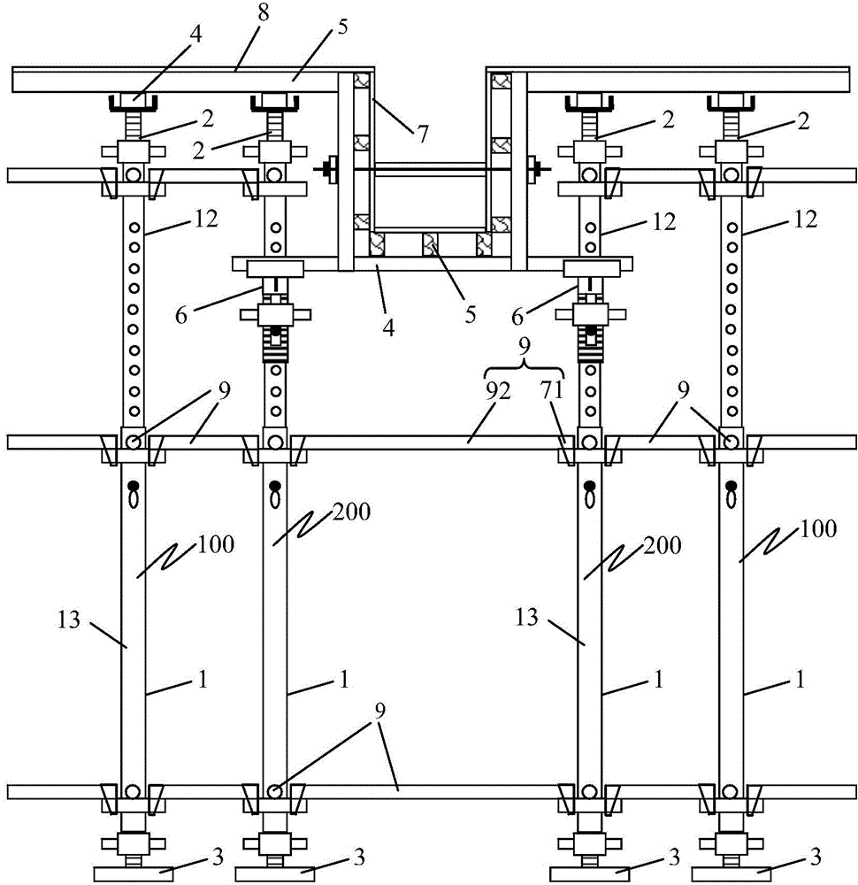
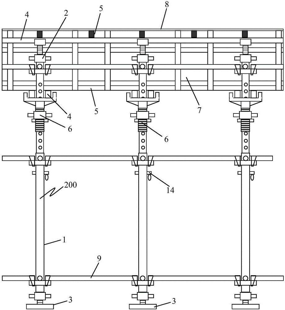
[0039] see Figure 1 to Figure 10 As shown, a construction method of a concrete beam slab formwork support system of the present invention, the support system includes a plurality of groups of support rod assemblies, each group of support rod assemblies includes: a first support rod assembly 100 and a second support rod assembly 200; The first support rod assembly 100 includes a telescopic support pole 1, an adjustable jack 2, an adjustable base 3, and a joist 4; the telescopic support pole 1 is provided with a plurality of trays 11; the first The second support rod assembly 200 is provided with a girder 6 on the telescopic support pole 1 of the first support rod assembly 100; A plurality of holes 121 are arranged at a certain distance from top to bottom, a tray 11 is provided near the upper end of the inner casing 12; a tray 11 is respectively set near the upper and lower ends of the outer casing 13, and a through hole 131 is arranged below the upper tray 11 of the outer casi...


PUM


Abstract

The invention provides a construction method of a support system for templates of concrete beams and slabs. The support system comprises a plurality of groups of support rod components, wherein each group of support rod components comprises a first support rod component and a second support rod component; the first support rod component comprises a telescopic support upright rod, an adjustable top support, an adjustable base and a support beam; the telescopic support upright rod is sheathed by a plurality of trays; the second support rod component is formed by arranging a beam support on the telescopic support upright rod of the first support rod component; the telescopic support upright rod comprises an inner casing pipe and an outer casing pipe; a plurality of holes are formed in the inner casing pipe at certain intervals from top to bottom; a tray is arranged near the upper end of the inner casing pipe; two trays respectively sleeve near the upper end and the lower end of the outer casing pipe; a through hole is formed in the lower part of the upper stray of the outer casing pipe; all the parts of the support system are constructed according to the construction structure diagram. The support system is simple in structure and convenient to be operated; the construction quality is improved.

Description

technical field [0001] The invention relates to the technical field of construction engineering, in particular to a construction method for a concrete beam-slab formwork support system. Background technique [0002] At present, in construction projects, for the support system of concrete beam and slab formwork, most of them use fastener-type steel pipe scaffolding or bowl-buckle-type steel pipe scaffolding. Then lay joists on the adjustable jacking, set joists on the joists, and then install beam-slab formwork on the joists. In this support system, the support poles of the beam formwork and the support poles of the slab formwork cannot be shared, resulting in The amount of support poles increases, and it is difficult to erect the support poles of the beam-slab formwork, resulting in complex installation process and low installation efficiency. When the formwork support pole adopts the traditional adjustable steel pipe column, because the diameters of the inner sleeve and th...

Claims


Application Information

Patent Timeline
IPC IPC(8): E04G11/48E04G11/56
Inventor 周继忠郑永乾庄金平郑莲琼蔡雪峰张雪丽温骏荣温选珍詹铃光
Owner FUJIAN UNIV OF TECH
Learn More