
Free-piston Stirling heat engine

A technology of piston and heat engine, which is applied in the field of free piston Stirling heat engine, can solve problems such as the jamming of the ejector and the ejector cylinder, deformation of the ejector cylinder, and strict manufacturing process requirements, so as to achieve the suppression of structural asymmetry and smooth flow , reduce the effect of cylinder material

Inactive Publication Date: 2015-05-27
TECHNICAL INST OF PHYSICS & CHEMISTRY - CHINESE ACAD OF SCI +1
View PDF6 Cites 3 Cited by
  • Summary
  • Abstract
  • Description
  • Claims
  • Application Information

AI Technical Summary

Problems solved by technology

[0020] The purpose of the present invention is to provide a free-piston Stirling heat engine to simplify the structure of the heat exchanger at the heat release end, the regenerator and the heat exchanger at the heat absorption end, improve the reliability of the system, and reduce the process difficulty and manufacturing cost of the system. And it can overcome the defects of the above-mentioned free-piston Stirling heat engine that the ejector and the ejector cylinder are stuck, the ejector cylinder is deformed, the material of the cylinder body and the manufacturing process are strict, etc.

Method used


Image

  • Free-piston Stirling heat engine
  • Free-piston Stirling heat engine
  • Free-piston Stirling heat engine

Examples


Embodiment Construction

[0043] In order to make the purpose, technical solutions and advantages of the present invention more clear, the present invention will be further described below in conjunction with the accompanying drawings and embodiments; obviously, the described embodiments are some embodiments of the present invention, not all embodiments. Based on the embodiments of the present invention, all other embodiments obtained by persons of ordinary skill in the art without making creative efforts belong to the protection scope of the present invention.

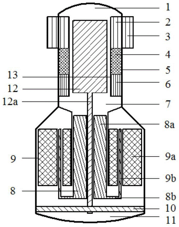
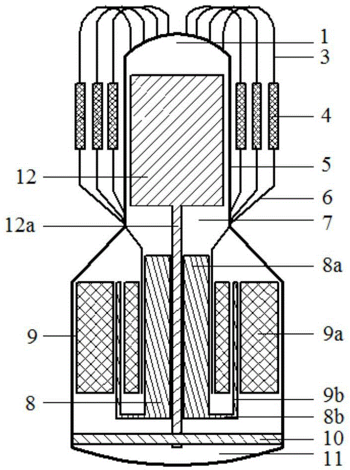
[0044] image 3 It is a structural schematic diagram of a free-piston Stirling heat engine provided by an embodiment of the present invention, image 3 and figure 1 The same components are given the same reference numerals. Such as image 3 As shown, the free-piston Stirling heat engine provided in this embodiment includes: a cylinder body 5, a linear oscillating motor 9, a power piston 8 and an ejector 12 arranged in the cylinder body 5; t...


PUM


Abstract

The invention relates to a free-piston Stirling heat engine. The free-piston Stirling heat engine comprises a cylinder body, an evacuator, a power piston and a linear oscillating motor, wherein the evacuator and the power piston are arranged in the cylinder body; the power piston consists of a piston cock body and a piston tenon part, the piston cock body is arranged in the cylinder body, the piston tenon part is connected with a motor rotor of the linear oscillating motor, an expansion chamber is formed between the evacuator and a first end of the cylinder body, a compression chamber is formed between the evacuator and the power piston, and a heat absorption end heat exchanger, a heat regenerator and a heat release end heat exchanger, which are of pipe bundle structures and are not in contact with the cylinder body, are arranged in an outer-side circumference space of the cylinder body. According to the heat engine, the cylinder body at the outer side of the evacuator cannot be subjected to extrusion deformation by the heat regenerator, so that the mechanical damping and air leakage loss of the evacuator are reduced; meanwhile, the room-temperature side temperature of the evacuator can be effectively lowered, so that the phenomenon that the mechanical damping of the evacuator is increased, and even that the evacuator and an air cylinder are stuck, due to heat leakage is avoided; a high-temperature-end heat exchanger, the heat regenerator and a room-temperature-end heat exchanger all adopt small-diameter pipe bundle structures, so that the requirements on materials can be effectively lowered, and the manufacturing cost is effectively reduced.

Description

technical field [0001] The invention relates to the technical field of thermal power, in particular to a free-piston Stirling heat engine. Background technique [0002] The free-piston Stirling heat engine is a special structural form of the thermoacoustic heat engine, which realizes the conversion between external heat and mechanical energy through the efficient Stirling cycle of the internal working medium. The free-piston Stirling engine using the forward Stirling cycle converts external heat energy into mechanical energy by expanding when heated, and compressing when it is cold; the free-piston Stirling refrigerator adopting the reverse Stirling cycle absorbs heat through expansion and releases heat through compression Heat is pumped from the low temperature side to the room temperature side to achieve cooling effect. Whether it is an engine or a refrigerator, the theoretical efficiency of this type of heat engine is equal to the Carnot efficiency. As a thermoacoustic ...

Claims


Application Information

Patent Timeline
Patent Type & Authority Applications(China)
IPC IPC(8): F02G1/043
CPCF02G1/0435F02G1/055F02G1/057
Inventor 罗二仓余国瑶戴巍刘斌
Owner TECHNICAL INST OF PHYSICS & CHEMISTRY - CHINESE ACAD OF SCI
Learn More