
An energy recovery device for head-on airflow of an electric vehicle

An energy recovery device and head-on airflow technology are applied to electric vehicles, the conversion of air flow to electric energy, and vehicle energy storage. stable effect

Inactive Publication Date: 2018-01-16
JIANGSU UNIV
View PDF8 Cites 0 Cited by
  • Summary
  • Abstract
  • Description
  • Claims
  • Application Information

AI Technical Summary

Problems solved by technology

However, in the process of converting wind energy to electric energy on electric vehicles, the first problem to be solved is whether the conversion can be performed. If the aerodynamic resistance of the vehicle is greatly increased in order to collect wind energy, such wind energy recovery is not feasible

Method used


Image

  • An energy recovery device for head-on airflow of an electric vehicle
  • An energy recovery device for head-on airflow of an electric vehicle
  • An energy recovery device for head-on airflow of an electric vehicle

Examples


Embodiment Construction

[0035] In describing the present invention, it is to be understood that the terms "upper", "lower", "front", "rear", "left", "right", "top", "bottom", "inner", "outer" ” and other indicated orientations or positional relationships are based on the orientations or positional relationships shown in the accompanying drawings, which are only for the convenience of describing the present invention and simplifying the description, rather than indicating or implying that the referred device or element must have a specific orientation, with a specific configuration and operation, and therefore should not be construed as limiting the invention.

[0036] In addition, the terms "first" and "second" are used for descriptive purposes only, and cannot be interpreted as indicating or implying relative importance or implicitly specifying the quantity of indicated technical features. Thus, a feature defined as "first" and "second" may explicitly or implicitly include one or more of these featu...


PUM


Abstract

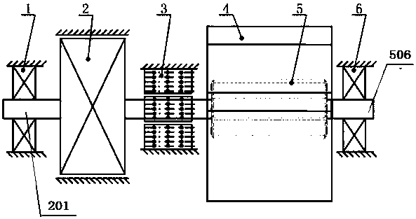
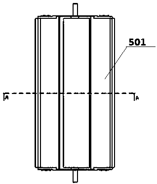
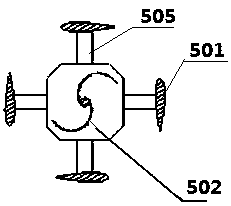
The invention belongs to the field of wind energy utilization and relates to an electric vehicle head airflow energy recovery device, a generator, a wind energy concentration device and a wind turbine; the wind energy concentration device is a pipe with a wide inlet and outlet at both ends and a narrow middle, and is placed in the front cabin of the car. The inlet is located behind the air intake grille of the car, and the outlet is set at the bottom of the front cabin of the car; the wind turbine is installed in the wind energy concentration device, the generator and the wind turbine are connected through permanent magnetic bearings, and the ends of the wind turbine and generator are respectively connected with rolling bearings; The machine is a combination of lift-type blades and resistance-type blades, which improves the start-up performance and actual operation performance of the wind turbine; when the electric vehicle is driving, the airflow entering the front compartment of the vehicle from the air intake grille is first introduced into the wind energy concentration device, and passes through the concentration device. The rectification and speed-up effects of the optimized flow field are optimized; the optimized airflow flows to the blades of the wind turbine to drive the wind turbine to rotate, and the generator starts to work driven by the wind turbine to realize the conversion of wind energy into electrical energy.

Description

technical field [0001] The invention relates to the field of wind energy utilization, in particular to an energy recovery device for an electric vehicle's oncoming airflow. Background technique [0002] Facing the increasingly severe environmental and energy crisis, most countries in the world have turned the future development of the automobile industry to new energy vehicles featuring energy saving and environmental protection. After entering the 21st century, the Chinese government has attached great importance to the development of new energy vehicles, and the national policy has obviously begun to tilt towards pure electric vehicles. [0003] The development direction of electric vehicles receiving key support is clear, but the development of electric vehicles faces many practical problems, such as insufficient cruising range, lack of sufficient charging stations, and so on. For consumers in China, range is an important consideration when purchasing an electric vehicle...

Claims


Application Information

Patent Timeline
Patent Type & Authority Patents(China)
IPC IPC(8): F03D9/25F03D3/04F03D3/06F03D80/70B60L8/00
CPCF03D3/0427F03D9/25B60L8/006F03D3/062Y02E10/74Y02T10/7072
Inventor 江浩斌李傲雪马世典
Owner JIANGSU UNIV
Learn More