Shock-absorption buffer shaft and application

A buffer shaft, input shaft technology, applied in the direction of couplings, elastic couplings, vehicle parts, etc., can solve the problem of not being able to withstand two-way action, vibration damping and shock resistance, smooth torque output, energy-absorbing materials that absorb less impact energy, Secondary impact and other problems, to achieve the effect of reducing impact stress, smooth torque output, and prolonging service life

Inactive Publication Date: 2015-05-27
金余和
View PDF7 Cites 10 Cited by
  • Summary
  • Abstract
  • Description
  • Claims
  • Application Information

AI Technical Summary

Problems solved by technology

Combining the various couplings mentioned above, their function is to reduce the impact and protect the shaft system with different material properties at the peak time. However, due to the small rotation angle difference of the shaft, the energy-absorbing material absorbs less impact energy, and the impact energy is prolonged over time. Frequent load changes lead to wear and looseness, resulting in secondary impacts, not to mention bidirectional effects of vibration reduction, shock resistance, and smooth torque output

Method used


Image

  • Shock-absorption buffer shaft and application
  • Shock-absorption buffer shaft and application

Examples


Embodiment Construction

[0026] The present invention will be further described below in conjunction with drawings and embodiments.

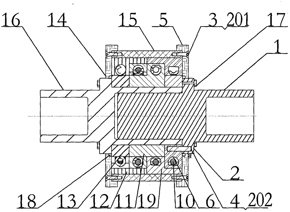
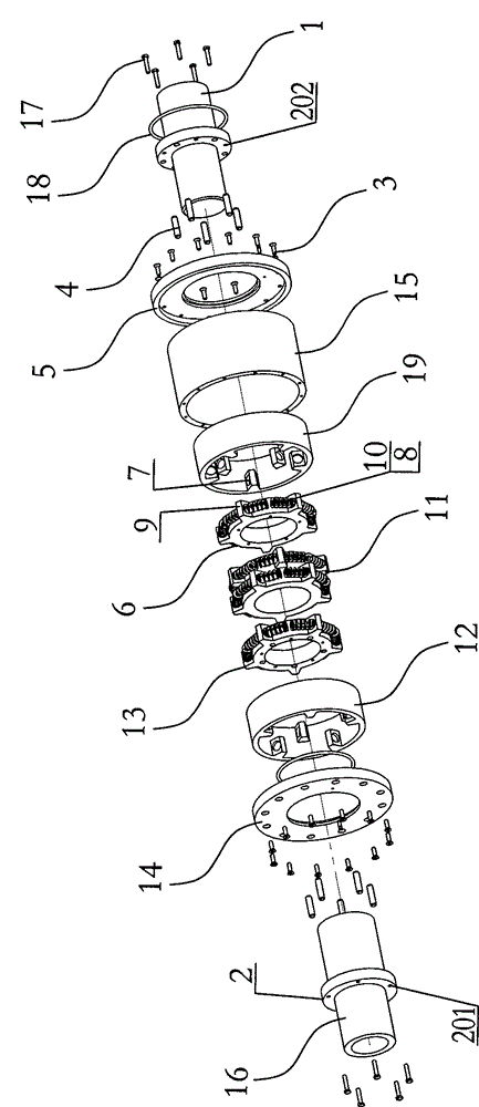
[0027] figure 1 , 2 As shown: a shock absorbing buffer shaft includes an input shaft 1, a fastening bolt 3, a force transmission pin 4, an input end cover 5, an input tooth plate 6, a spring 10, an input tooth cover 19, a double tooth plate 11, an output tooth set 12, Output tooth plate 13, output end cover 14, outer casing 15, output shaft 16, limit screw 17 and O-shaped sealing ring 18.

[0028]Both the input shaft 1 and the output shaft 16 are provided with a ring of flange flanges 2, and a plurality of limit screw holes 201 are evenly opened on the two flange flanges 2, and the two opposite inner end surfaces of the two flange flanges are uniformly arranged. There are a plurality of force transmission counterbores 202, and the plurality of force transmission counterbores 202 of the input shaft 1 are connected to the input crankset 6 through the force transmission ...


PUM


Abstract

The invention relates to a shock-absorption buffer shaft. The shock-absorption buffer shaft comprises an input shaft, an input end cover, a force transfer pin, an input toothed sleeve, an input toothed wheel, a double toothed wheel, a spring, an output toothed sleeve, an output toothed wheel, an output shaft, an output end cover, a limiting bolt, a fastening bolt and an external sleeve. Force is transferred to the input toothed sleeve by virtue of the teeth of the first internal toothed ring of the input toothed sleeve in a manner of compressing a spring through the teeth of an external toothed ring on the input toothed wheel, later the force is transferred to the double toothed wheel by virtue of the teeth of the first external toothed ring of the double toothed wheel in a manner of compressing the spring through the teeth of the second internal toothed ring of the input toothed sleeve, then the force is transferred to the output toothed sleeve by virtue of the teeth of the first internal toothed ring of the output toothed ring in a manner of compressing the spring through the teeth of the second external toothed ring of the double toothed wheel, and then the force is transferred to the output toothed wheel by virtue of the teeth of the external toothed ring of the output toothed wheel in a manner of compressing the spring through the teeth of the second internal toothed ring of the output toothed sleeve, and finally, the output toothed wheel is used for transmitting the torque by virtue of the force transfer pin through the output shaft.

Description

technical field [0001] The invention relates to a shaft structure, in particular to a shock-absorbing buffer shaft. Background technique [0002] No matter in the transmission system of any mechanical equipment, the impact peak load during frequent starting and braking and sudden load changes will lead to component failure and accumulated fatigue damage. The output vibration frequency of the prime mover can also cause resonance due to the coupling of the load frequency, resulting in Parts break and fail, causing accidents. In order to reduce vibration and shock resistance, in the background of the existing technology, there have been plum blossom couplings, diaphragm couplings, star couplings, tire couplings, flange finger couplings, Snake type spring coupling, splint spring coupling, flange groove type finger pin coupling. Combining the various couplings mentioned above, their function is to reduce the impact and protect the shaft system with different material properties...

Claims


Application Information

Patent Timeline
Patent Type & Authority Applications(China)
IPC IPC(8): F16D3/52F16D3/84F02C7/36B66D1/14B63H23/02F03D11/02B60K17/22
Inventor 金余和
Owner 金余和
Why Eureka
Try Eureka