Eureka AIR delivers breakthrough ideas for toughest innovation challenges, trusted by R&D personnel around the world.

Reciprocating compressor and method for driving same

A compressor, reciprocating technology, applied in the direction of machines/engines, liquid variable capacity machinery, mechanical equipment, etc., can solve the problems of increasing the vibration noise of the compressor, wear, emission noise and the vibration can not be effectively offset, etc. The effect of reducing vibration noise

Inactive Publication Date: 2015-05-27
LG ELECTRONICS INC
View PDF8 Cites 7 Cited by
  • Summary
  • Abstract
  • Description
  • Claims
  • Application Information

AI Technical Summary

Problems solved by technology

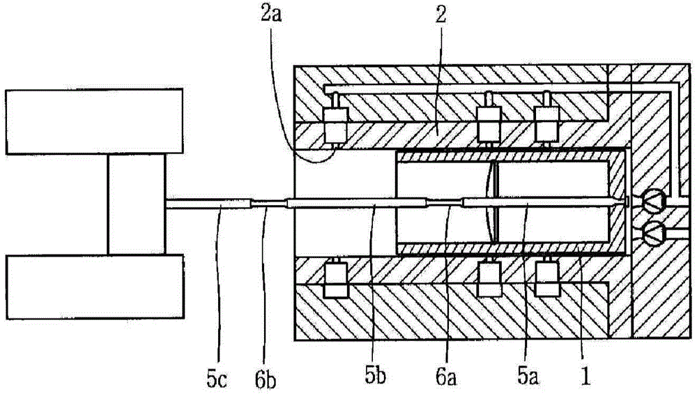
[0007] However, in the prior art reciprocating compressor, impurities mixed with the refrigerant gas are introduced into the fluid bearing, clogging the fluid bearing, thereby preventing the supply of refrigerant gas between the cylinder 2 and the piston 1
Therefore, the concentricity between the piston 1 and the cylinder 2 is broken, causing friction loss and wear when the piston 1 closely adheres to the cylinder 2 for reciprocating motion
[0008] Also, when high-temperature refrigerant discharged from the compression space is introduced into the fluid bearing to heat the cylinder 2, the specific volume of the compression space increases, and thus causes a suction loss
[0009] In addition, the discharge noise and vibration generated by the compressed refrigerant in the compression space cannot be effectively offset, thus increasing the vibration noise of the compressor

Method used


Image

  • Reciprocating compressor and method for driving same
  • Reciprocating compressor and method for driving same
  • Reciprocating compressor and method for driving same

Examples


Embodiment approach

[0096] Meanwhile, the previous embodiment shows that the filter unit is provided on the passage of the refrigerant gas to filter foreign matter before the refrigerant gas is introduced into the air hole. However, these embodiments show that when the compressor is continuously operated for a predetermined period, the cylinder is vibrated periodically to remove foreign matter stuck in the air hole of the cylinder, thereby preventing clogging of the air hole in advance.

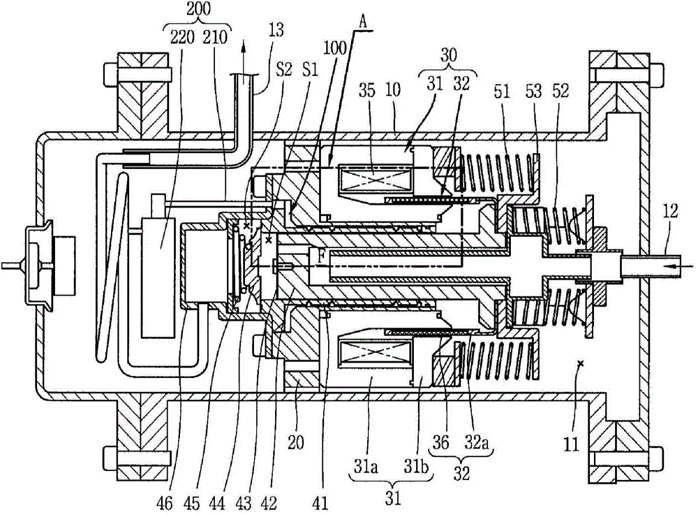
[0097] Figure 12 is a longitudinal sectional view showing a main part of another embodiment of a fluid bearing for a reciprocating compressor according to the present invention, Figure 13 is shown based on Figure 12 A schematic diagram of the foreign matter removal structure of the compressor controller, and Figure 14 is shown based on Figure 13 A block diagram of the foreign body removal process.

[0098] For example, if Figure 12 to Figure 14 As shown in , the operation duration t1 of the compressor...


PUM


Abstract

The present invention relates to a reciprocating compressor. The present invention can prevent friction loss or abrasion between a cylinder and a piston, which is caused when a hydraulic bearing is blocked with a foreign substance, by preventing the foreign substance mixed in refrigerant gas from flowing into the hydraulic bearing, and can improve compressor performance by preventing a specific volume in a compression space from increasing when high-temperature refrigerant gas discharged in the compression space is cooled, such that vibration noise of the compressor can be reduced since a gas guiding part offsets vibration and the noise generated when a refrigerant is discharged in the compression space. Furthermore, the number of vibrations of a mover is increased and a driving operation for removing foreign substances is carried out to increase the number of vibrations of a cylinder such that any foreign substance stuck in a gas hole can be cleaned, thereby increasing performance and reliability of the compressor.

Description

technical field [0001] The present invention relates to a reciprocating compressor, and more particularly to a reciprocating compressor having a fluid bearing, and a method for driving the same. Background technique [0002] Generally, a reciprocating compressor is used to suck in, compress and discharge refrigerant while a piston linearly reciprocates in a cylinder. The reciprocating compressor may be classified into a connection type reciprocating compressor and a vibration type reciprocating compressor according to a method for driving a piston. [0003] In a linked reciprocating compressor, a piston is connected to a rotating shaft associated with a rotary electric machine through a connecting rod, which causes the piston to reciprocate in a cylinder, thereby compressing a refrigerant. On the other hand, in the vibration type reciprocating compressor, the piston is connected to a mover associated with the reciprocating compressor, which vibrates the piston as it recipro...

Claims


Application Information

Patent Timeline
Patent Type & Authority Applications(China)
IPC IPC(8): F04B17/04F04B53/20F04B35/04H02K41/02H02P25/06
CPCF04B39/0292F04B39/16F04B2205/501F04B49/065F04B35/045F04B49/20F04B53/20F04B17/03F04B35/04F04B53/004
Inventor 寄成铉卢基元安光运朴景培全时汶朴濬成
Owner LG ELECTRONICS INC
Why Eureka
Eureka Blog
Learn More