Unit and casing with a cooling jacket

A technology of cooling jacket and shell, applied in the direction of casing/cover/support, electromechanical device, electrical components, etc., can solve the problem of processing labor and other problems, and achieve the effect of eliminating reprocessing, efficient heat transfer, and high cooling efficiency

Inactive Publication Date: 2015-05-27
VOLKSWAGEN AG
View PDF13 Cites 4 Cited by
  • Summary
  • Abstract
  • Description
  • Claims
  • Application Information

AI Technical Summary

Problems solved by technology

In addition, complex geometries can only be cast with sand co...

Method used


Image

  • Unit and casing with a cooling jacket
  • Unit and casing with a cooling jacket
  • Unit and casing with a cooling jacket

Examples


Embodiment Construction

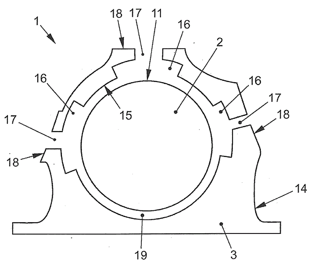
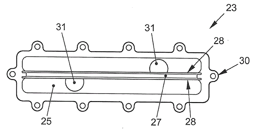
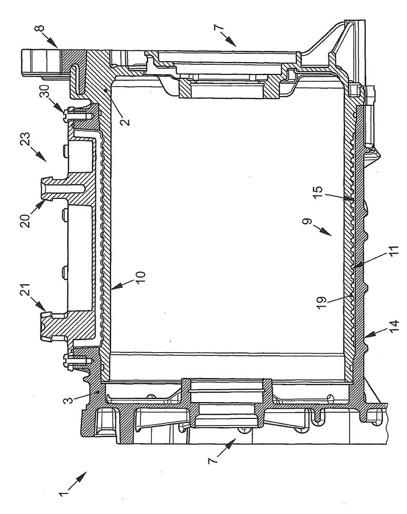
[0039] Figures 1 to 4 shows the housing 1 for the motor, which consists of the figure 1 and 2 The internal part shown in 2 and the image 3 3 components shown in the outer part. Figure 4 The housing 1 is shown with an inner part 2 and an outer part 3 . The housing 1 has a cooling jacket in which a coolant circulates and which receives and dissipates the heat of the electric motor. According to the invention such a housing can also be used for other heat sources or coolers to be cooled. The housing 1 according to the invention is described by way of example with the application of an electric motor. The motor includes a stator 4 and a rotor 5 . The rotor 5 is connected to a shaft 6 , which is fixed in the housing 1 for rotational movement via bearings 7 . The housing 1 consists of an inner part 2 and an outer part 3 , which conduct coolant.

[0040] figure 1 , 2 4 and 4 show the inner part 2, which comprises a bearing end shield 8 and a pipe section 9 having a pipe ...


PUM


Abstract

The invention relates to a casing (1) with a cooling jacket for a unit, particularly for an electric motor, comprising an inner part with a tube section and an outer part (3) for receiving the tube section, wherein the tube section is rotationally symmetrical. The invention also relates to an electric motor with such a casing (1), wherein a cover (23) is fixed, in flow-tight manner, on an opening (17) of the casing (1) between the cooling jacket and the ambient environment. At least one device, such as a supply connection (20) and/or a discharge connection (21) and/or a separating board (24) and/or an assembly to be cooled, is arranged on the cover (23).

Description

technical field [0001] The invention relates to a device, which may be formed by an electric motor, and to a housing for the device with a cooling jacket. Background technique [0002] In devices with housing cooling, for example in electric motors, the device is enclosed in a two-part housing. The intermediate space, the so-called cooling jacket, formed between the housing parts serves to accommodate and conduct the coolant. [0003] The development of cooling jackets for electric motors, in particular as drive units for electric vehicles, places special demands on researchers. The manufacture of such a device is to be simple and to be realized with little material, mechanical and time outlay. In the devices known from the prior art, the shaping of the cooling jacket always involves higher costs in the tolerable machining. [0004] In order to simplify the machining of the two-body housing, attempts are made to use components or at least component segments with simple ge...

Claims


Application Information

Patent Timeline
IPC IPC(8): H02K5/20
CPCH02K5/203
Inventor H.韦尔-布鲁恩G.阿龙佐M.蓬特
Owner VOLKSWAGEN AG
Why Eureka
Try Eureka